Hi,
Why do remote sense PSU's not give details about the remote sense circuitry inside the module?
The info is needed.
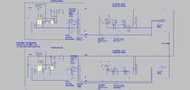
As you can see from the attached, the resistor valuss are needed, or else they may interfere with any load share resistors used.
Eg
...no details of remote sense
Why do remote sense PSU's not give details about the remote sense circuitry inside the module?
The info is needed.
As you can see from the attached, the resistor valuss are needed, or else they may interfere with any load share resistors used.
Eg
...no details of remote sense