Wassup guys,
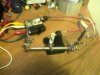
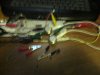
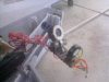
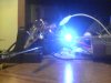
I made the circuit below, and it worked perfectly......but just once out of 10 times... I would get some sparks, and then it kinda look like it turn off and doesn't work for a while for no reason. Sometimes it works 3 times in a row, sometimes nothing. The connections seem okay, the polarity seems fine also since it already worked. So basically I just don't get a whine or a sound everytime I put my power supply on.
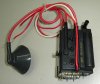
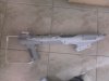
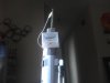
I'm using a new flyback (picture below) with a MJE13009 transistor. The transistor seems fine also, doesn't even need a heatsink. I don't if there is any kind of capacitor in there so it has to discharge or something. Can you guys help me with this ?
Thank you !
I made the circuit below, and it worked perfectly......but just once out of 10 times... I would get some sparks, and then it kinda look like it turn off and doesn't work for a while for no reason. Sometimes it works 3 times in a row, sometimes nothing. The connections seem okay, the polarity seems fine also since it already worked. So basically I just don't get a whine or a sound everytime I put my power supply on.
I'm using a new flyback (picture below) with a MJE13009 transistor. The transistor seems fine also, doesn't even need a heatsink. I don't if there is any kind of capacitor in there so it has to discharge or something. Can you guys help me with this ?
Thank you !