I recently made a circuitboard and insterted a Pic 16f628a microchip in it. When I tested it with running an LED over the positive and negative it works, yet when I try to run it over a pin that I programmed to send voltage to by holding the LED over the positive and negative, it doesn't work. It worked on my programmer (that comes with LEDS to show outputs) and I've included the source.
Continue to Site
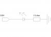
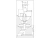
") Yeah my problem probably is on my PCB. I'm also wondering if the "reset" part of my program has anything to do with it not working on my PCB. Anyway; I've attatched the schematics for the exact layout on my PCB. Although I've already showed how the connection for RB0 is done, and its the same for Rb1... ect.
Yeah my problem probably is on my PCB. I'm also wondering if the "reset" part of my program has anything to do with it not working on my PCB. Anyway; I've attatched the schematics for the exact layout on my PCB. Although I've already showed how the connection for RB0 is done, and its the same for Rb1... ect.