Hello I am a very, very, very non-electronic person, so I thought I could do a simple task of making a LED circuit, but I guess I was wrong. I am running this off of a 13.8V source, theres 4 blue LEDS (3.2V ea), and I have a 1/8 watt 56 ohm resistor. By all accounts this should light up I suppose but it didn't, the LEDs all were working and I can assume the resistor was as well, but when I hooked it up, nada. I assume the problem lies with my soldering since I am no expert in that area. Any ideas on how to fix this would be great! Thanks!
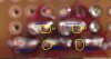
Pics of my circuit:
**broken link removed**
**broken link removed**
Pics of my circuit:
**broken link removed**
**broken link removed**
")