tempest411
New Member
Hello,
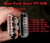
I have a Ford TFI system that I converted from a style that had a distributor mounted ignition module to a style used by Ford in later years which relocated the ignition module to the fender on a heat sink. I made the harness from scratch and used Motorcraft components. Upon completion I was very happy to see that it starts right up and runs great in it normal configuration. However, to set the base timing a removable jumper must be pulled from the SPOUT (Spark-Output) line, which takes control away from the computer and lets the module fire the ignition system at a fixed dwell. Mine will not do that unless I either goose the throttle while cranking and maintain it above 1500 rpm, or, as I discovered in the process of testing, install (back-probed) an LED test light between the distributor pickup output, called the 'PIP' and +12V. With that LED test light installed, it starts up and runs like a champ at base timing. I did find one author that mentioned this scenario (with the test light), and he stated that nine times out of ten it indicates the hall effect sensor in the distributor is bad. With that in mind, but being suspicious in my particular case as my distributor pickup was new, I made use of another distributor I had. I just plugged it in and spun the shaft. I have a spark tester between the coil and the distributor cap. It mirrors exactly what is happening with the distributor installed in the engine. I have also changed the ignition module, and loop checked all the wiring. I have looked for shorts to ground where they shouldn't be, and between all pathways to insure they are not shorted together. The only time I can get the module to perform it's switching function to the coil properly (without the LED test light installed), is to change the load-I experimented with a 12V incandescent bulb (#194) in place of the coil. The coil does check out as far as primary and secondary resistance, and is also new...One peculiar thing I noticed is that-with the LED test light removed, coil connected-if I happen to stop the distributor shaft at a place where the shutter is in the Hall Effect sensor, the coil will start firing repeatedly on it's own, with no distributor shaft rotation, but will stop if you rotate the distributor shaft so the shutter is no longer in the sensor, or you connect the LED light. I'm pretty much at my wit's end at this point. It's not that complicated a circuit! I suppose if I could find out hat the LED is actually doing for this circuit I could find out where the problem is...Any suggestion are very appreciated!
Rick