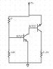
I builded this circuit into a proptotipe board to see how it worked before final design. when I set R=10ko, Q1 was active, and Q2 was saturated. When I set R=330ko, Q2 blows up (I mean really, in a few seconds transistor blows and stops working, of course)...
why did this happend?? Shouldn't if have to turn Q1 off, and so Q2 ??
How do I calculate Ib and Ic in Q1 using this circuit??
thnaks
why did this happend?? Shouldn't if have to turn Q1 off, and so Q2 ??
How do I calculate Ib and Ic in Q1 using this circuit??
thnaks