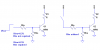
I was adviced by an engineer that in addition to a resistor one of its legs connected to Vsource and second to Base, to connect another resistor from Base to ground.
1. Why is it recommended?
2. Should the resistor be very large so the Vsource (MCU GPIO pin) wont source large current?
Thank you.
1. Why is it recommended?
2. Should the resistor be very large so the Vsource (MCU GPIO pin) wont source large current?
Thank you.