Continue to Site

Welcome to our site!

Electro Tech is an online community (with over 170,000 members) who enjoy talking about and building electronic circuits, projects and gadgets. To participate you need to register. Registration is free. Click here to register now.

  • Welcome to our site! Electro Tech is an online community (with over 170,000 members) who enjoy talking about and building electronic circuits, projects and gadgets. To participate you need to register. Registration is free. Click here to register now.

Which way to do it?

Status
Not open for further replies.

jimfraseruk

New Member
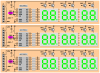
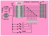
I am trying to write a multi event timing device. Upto three dog agility rings will be timed at once, each with start/ finish gate (IR Beam Break). Those start/ finish signals will be sent to a central timing device. This will calculate and transmit times to a PC via USB and start large LED displays for each ring to show spectators each dogs time.

Sounds like a huge project to me but I am breaking this down into small projects as I am a beginner.

I initially copied a stopwatch type program (posted on this site, thankyou!) that uses TMR2 interrupts to count 1/100ths of a second which worked well. But I want three timers running at the same time so I changed it so that there are three Start/Stop buttons. When a button is pressed the start time is saved to a register (just like a timestamp) on the next button press the finish time is saved. I then subtract them to find the elapsed time.

1. Problem is that I cannot release the buttons quickly enough so it starts/ stops the time (not TMR2) many times before finally starting properly. I don't think I can use a delay or wait for a release, as a trigger from another ring may be missed. As this bouncing will occur at both the start and finish of the timing maybe they cancel each other out. What does your experience tell you I should do?

2. Should I abandon the datalogging approach (finish time - start time) and do everying in the interupt routine? I am worried an interupt may occur in the middle of saving the datalogged start/ stop time. I cannot save the registers as they must increment. I could have three incrementing counters in the interupt using a 'flagrunning' and 'flagbuttonpressed' for each ring to determine if I count or not, but then I could be out on the timing by max 10ms as I wait for an interupt to start timing. I am not sure which method would have the most accurate times. Recommendations please.

3. Should I do this all another way as I the dog people may want to scale to more rings?

I am a beginner so be gentle (probably inefficient code) and all this is being done in the simulator until the parts arrive and I have learnt more.
 

Attachments

  • StopWatchMain628a.asm
    23.3 KB · Views: 117
Firstly, for a beginner, your code looks pretty good.

A few observation/questions,
Do you need the overflow ability, with a 24 bit counter overflow will only happen after 2 days. Will any event last more than 2 days?
The Olympics is timed to 1/100th of a second. Human reaction time is typically 0.2 seconds. I don't think you need to worry about the possible errors.
You are right to worry about interrupts coming along at the wrong time. If an IRQ happened while you are copying the counter then it could be out be as much as 10 minutes - more likely (but still remote) 2.5 seconds.

A way to fix the counter and debounce problem would be,

Put a flag in your ISR that is set when it triggers. (bsf Flags,TimeUp)
Use this flag to halt your main code,
Code:
loop		btfsc	Flags,TimeUp
		goto	loop
		bcf	Flags,TimeUp
You can now implement a very simple debounce that doesn't rely on a delay,
Code:
		movfw	SW_PORT;	get keys
		movwf	TEMP_KEYS;	store for later
		xorwf	OLD_KEYS,W;	keep only keys that have changed
		andwf	TEMP_KEYS,W;	get rid of keys that have been released
		movwf	KEY_PRESSED
		movfw	TEMP_KEYS;	copy keys for next time
		movwf	OLD_KEYS

; at this point KEY_PRESSED contains a 1 for any key that is pressed.
; it will only contain a 1 for a new key press. A held down key will be 0 (after being 1 once).

You can also safely read/write to your counter variables as an IRQ will not be along for another 10mS and your code will be finished in uS.

Mike.
 
Thankyou for the advice.

I think I understand the debounce code (testing tonight will clear it up) but am not sure about the flag in the ISR.

I think you are saying that the button statuses are only checked after each interrupt (as identified by the flag 'TimeUp') otherwise the main loop just wastes time. Then as you say I would have loads of time to do things before the next interrupt, but there would be a continuous error of 0-10ms (much better than 10min or 2.5 secs). However should the code not read

Code:
loop   btfss    Flags,TimeUp ; rather than btfsc
       goto     loop         ; as it would never get out of
       bcf      Flags,TimeUp ; the loop
Could I reduce the 10ms error by working out how many times I loop and adding that to the final time for each couter? Eventually human reaction time errors will be removed through an IR beam break start/ stop signal.

I had the overflow in there just in case (practice for the future).

Thanks for the confidence boost on the code. It can only be good due to all the information on forums like this that I have scoured (plagiarised) for the last two weeks. It’s a steep learning curve but still fun at the moment. The RF and USB sections may be a bit more difficult though.
 
Last edited:
Your one PIC has to do both USB data transfer and timing for three rings. It is not easy.

PICs are becoming so cheap(less than a dollar for smaller ones) that it is now possible to use several to complete a complex task. This is not a commerical product that thousands are to be made and every component counts.

Of course an expert programmer can get everything done with a single PIC but there is no law against using several of them to ease programming, especially for beginners.

I would use one large PIC solely for USB and take care of data transfer between other smaller PICs each dedicated for timing. This approach scales up nicely too if additional rings are added later.
 
I agree.

I am thinking of changing the architecture so each ring has its own timer and large LED display. Then each ring sends its elapsed time to a central USB enabled PIC (via RF). This would be very scalable.

Although reading the USB PIC forums I may have to revert back to serial connection due to the compelxity of USB. One step at a time though.
 
There's more than enough horse power in a single PIC to meet those meager goals (grin). You can easily drive up to forty two (42) 7-segment displays to full brightness with an 8 pin bus (Port B) while using only about 5% processor "overhead" in the display interrupt driver. Use the same 1-msec Timer 2 display driver interrupt to debounce switches (24-msecs debounce should be enough) and to increment the three counters (once every 10 milliseconds or every 10 interrupt cycles). Here's example code for one of the three counters;

Code:
;
; unsigned char Clock1 [] = { 23, 59, 59, 99 };
;
; if (Clock1_switch)              // if Clock1 running
; { if (Clock1[3]++ = 99)         // if hundreths overflow (post inc hundreths)
;   { Clock1[3] = 0;              // reset hundreths and increment time
;     unsigned char n = 2;        // index for seconds element
;     while (Clock1[n]++ == 59)   // while value 59 (post inc value)
;       Clock1[n--] = 0;          // set to 00 and bump array index
;   }
; }
;
ISR_CLK1
        btfss   Switch1         ; switch 1 set (clock 1 enabled)?
        goto    ISR_CLK2        ; no, branch, else
        movf    Clock1+3        ; hundreths digit
        incf    Clock1+3,F      ; post increment hundreths
        xorlw   d'99'           ; done (no overflow)?
        bnz     ISR_CLK2        ; yes, branch, else
        movlw   Clock1+2        ; index for seconds element
        movwf   FSR             ; setup for indirect access
ISR_Bump1
        movf    INDF,W          ; while (Clock1[n]++ == 59)
        incf    INDF,F          ;
        xorlw   d'59'           ;
        bnz     ISR_CLK2        ;
        clrf    INDF            ;   Clock1[n] = 0;
        decf    FSR,F           ;   n--;
        goto    ISR_Bump1       ;
;
ISR_CLK2
 

Attachments

  • Dog Ring Display.PNG
    Dog Ring Display.PNG
    64.7 KB · Views: 146
  • Dog Ring Controller.PNG
    Dog Ring Controller.PNG
    23 KB · Views: 166
Last edited:
jimfraseruk said:
I agree.

I am thinking of changing the architecture so each ring has its own timer and large LED display. Then each ring sends its elapsed time to a central USB enabled PIC (via RF). This would be very scalable.

Although reading the USB PIC forums I may have to revert back to serial connection due to the compelxity of USB. One step at a time though.

You might consider using that $20 USB-to-TTL serial adapter from FTDI. Just plug it into the PIC serial port and you're done...
 
My idea to the OP had taken into account the distance between the rings, the cost of running cables(both start/stop signals and LED display) from individual ring to a central location and the possible consequence of component failure. I consider a distributed self-contained system is best for the OP as I'm pretty sure money, large sum of it, change hands depend on the correct working of each of these displays. A system wise failure is not so good than a single ring failure. Also the price of a PIC(16F628a) is likely to be cheaper than a few meter of multicore cable.
 
Last edited:
K8LH has a very good point.

Using a USB to TTL adapter is a far better solution than a PIC with USB, although it cost more.
 
Last edited:
eblc1388 said:
My idea to the OP had taken into account the distance between the rings, the cost of running cables(both start/stop signals and LED display) from individual ring to a central location and the possible consequence of component failure. I consider a distributed self-contained system is best for the OP as I'm pretty sure money, large sum of it, change hands depend on the correct working of each of these displays. A system wise failure is not so good than a single ring failure. Also the price of a PIC(16F628a) is likely to be cheaper than a few meter of multicore cable.
You may very well have provided the best solution. The OP never gave us distance info' though he implied there were some distances involved.

I just wanted to provide a different perspective and potential solution and suggest that it might not necessarily be a complex task.

Mike
 
Last edited:
Thankyou for all the replies. Sorry I did not provide distance info.

Each ring is probably 7mx7m and there are three of them at the moment. The admin person sits in the middle collecting times on bits of paper (from hand stopwatches).

I will look into the USB to TTL convertor.
 
Status
Not open for further replies.

Latest threads

New Articles From Microcontroller Tips

Back
Top