I've been trying to build a usable crystal controlled "bug" a few times but have always failed miserably Now I'm going to give it another go, but it would obviously be a good thing to know whether the circuits would work in the first place , and if they should but won't, then where will I have <snip> up... I've found four circuits so far, have been unsuccessful at building the first two, and would really appreciate it if someone could take a look at these (where'd I mess up?), and also the other two (as in would they work, there's no PCB drawings and laying out my own is a real *****...)
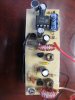
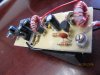
1: The Talking Electronics "Crystal locked bug" Crystal Locked FM Bug. Made two versions of it (TTH and SMD on my own PCB's since the original is just too damn big), the RF part was essentially same as the original (with the exception of a resistor instead of inductor in final amp/buffer stage), the audio stage was replaced with an LM386 in 200 gain mode. Couldn't get the SMD variety to work at all (might be my awzum sold3r1ng skillz...), the TTH did oscillate but didn't have any modulation (neither WB nor NB) though the 386 front end worked properly when connected to another, free-oscillating transmitter.
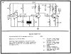
2: This one https://www.electro-tech-online.com/attachments/sp_18-jpg.42599/. Replaced the FET with a BF245C and tried a bunch of assorted varicaps and signal diodes for the SK3126 (no datasheet to be found for it anywhere), couldn't get it to work.
3: This: **broken link removed** Nothing really about it except "would it work", will probably also have to replace those "1 to 100pf or whatever" trimmers with smaller ones + fixed caps etc...
4: and this: **broken link removed**. Same question as above, also, should there be some sort of a trimming device in the first osc stage?
1: The Talking Electronics "Crystal locked bug" Crystal Locked FM Bug. Made two versions of it (TTH and SMD on my own PCB's since the original is just too damn big), the RF part was essentially same as the original (with the exception of a resistor instead of inductor in final amp/buffer stage), the audio stage was replaced with an LM386 in 200 gain mode. Couldn't get the SMD variety to work at all (might be my awzum sold3r1ng skillz...), the TTH did oscillate but didn't have any modulation (neither WB nor NB) though the 386 front end worked properly when connected to another, free-oscillating transmitter.
2: This one https://www.electro-tech-online.com/attachments/sp_18-jpg.42599/. Replaced the FET with a BF245C and tried a bunch of assorted varicaps and signal diodes for the SK3126 (no datasheet to be found for it anywhere), couldn't get it to work.
3: This: **broken link removed** Nothing really about it except "would it work", will probably also have to replace those "1 to 100pf or whatever" trimmers with smaller ones + fixed caps etc...
4: and this: **broken link removed**. Same question as above, also, should there be some sort of a trimming device in the first osc stage?
Last edited by a moderator: