Continue to Site

Welcome to our site!

Electro Tech is an online community (with over 170,000 members) who enjoy talking about and building electronic circuits, projects and gadgets. To participate you need to register. Registration is free. Click here to register now.

  • Welcome to our site! Electro Tech is an online community (with over 170,000 members) who enjoy talking about and building electronic circuits, projects and gadgets. To participate you need to register. Registration is free. Click here to register now.

Which Schottky for solar panel?

Status
Not open for further replies.
How did you work out 9%?

OK,
To cover the fully charged and discharged state of the battery,
ie: 13.8V and 10.8V, assuming for the test, the battery has an internal resistance of 0.1R

A solar cell with and emf of 17.5V and internal impedance of 5R.

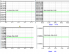
I ran LTSpice simulations for charged/discharged battery, charging currents using a closest match silicon diode and schottky diode.

See attached image:
The results show for 13.8V approx 11% and for 10.8V, 5%
If you take an average, it suggests an increase of 8%.... so I was 1% high in my rough calculation.

Does this answer you.?
 

Attachments

  • Solar1.png
    Solar1.png
    15.3 KB · Views: 177
Last edited:
Ref the miniscule current, if you do the calculations for a battery charge state over a voltage range of 10.8V [discharges] to 13.8V[charged] you see that the minsicule current can be as much as 9%... hardly miniscule.

The figures you supplied suggested the impedance of the solar panel is 5R and the current difference when a diode is replaced by a Schottkey diode, will be 8%.
But a solar panel does not work as you have suggested. When a normal power diode is replaced by a schottkey diode, the voltage across the load decreases by about 0.3v and this will cause a higher current to flow. The solar panel will not be able to deliver this current and consequently the voltage produced by the solar panel will also reduce and the current will remain almost exactly the same as before.

In other words, as I said, it does not mater if you use a power diode or Schottkey diode as the "reverse current" protection.

Ive come to the sad conclusion you havnt got a clue what you are talking about.
On this and on a number of other threads you are replying too.
If you want examples, just say and I'll repost some of your brightest and best offerings.

I think I would rather spend my time helping members who are prepared to listen and learn rather than keep trying to teach you the fundamentals of electronics.
 
Last edited:
I think you would be surprised by testing the actual circuit yourself with a solar panel and battery. The main difference between you and me is about 20 years. I have been teaching electronics for 40 years and no-one has challenged by comments, either in class or in any of my 25 books.
The fact that you went to a simulation program indicated you had absolutely no idea how the circuit works.
A solar panel is not a constant voltage device but a constant energy device (for the energy it is receiving). This is where you are making the mistake.

Why have you been editing out some of comments from your posts.?
and changing some to be in line with whats being said later by others.

To say you have been teaching electronics at all worries me.

One of your gems to a poster was
" an 'ac' current dosnt change direction, it just goes more or less"

and

"A capacitor when connected to a dc supply charges up to an 'opposite' polarity"

Regarding challenging your errors, a forum is a completely different ball game from a school environment where you have captive students, here we can speak our minds and tell you when we think you are talking nonsense.

Many members of this forum are mostly well informed and some are very experienced engineers and its a pleasure to discuss technical subjects and learn from each other.
 
Last edited:
I wonder if a P-channel power MOSFET with its gate wired to source would work. I've seen this used as a low drop diode on some robot designs.
 
I wonder if a P-channel power MOSFET with its gate wired to source would work. I've seen this used as a low drop diode on some robot designs.

hi Bill,
Ive got some info on file I'll dig it out and post.:)

EDIT: is that what you have in mind.
 

Attachments

  • Reverse_Batery_Protection.pdf
    149.6 KB · Views: 358
Last edited:
"A capacitor when connected to a dc supply charges up to an 'opposite' polarity"

Show me where I said the above.
 
"A capacitor when connected to a dc supply charges up to an 'opposite' polarity"

Show me where I said the above.

How can I when you have edited your post in order to hide it.??

At least try to be honest about you mistakes.:mad:
 
Well, you seem to have a quote from me. Where was the posting?

As far as the AC was concerned, I was considering a half-wave at the time as I was working on a cap driven supply and when I realised the mistake I corrected it.
 
Quote:
Originally Posted by colin55 View Post
I
When the capacitor is fully charged it produces a voltage equal to the charging voltage but of the opposite polarity.
hi,
I think this statement is misleading, it not 'opposite polarity', its the same polarity as the charging voltage.
__

Its from the 3rd of March.. Your ORIGINAL post not your edited version and my reply.

Is this clear enough for you.?
 
Last edited:
And what I said at the time was correct. I think the circuit was a battery electrolytic and resistor.

When the electrolytic charges, the voltage on the electrolytic is such that it opposes the charging voltage and that’s why the final current-flow is zero.
 
Well, you seem to have a quote from me. Where was the posting?

As far as the AC was concerned, I was considering a half-wave at the time as I was working on a cap driven supply and when I realised the mistake I corrected it.

Again you are fudging the posts.

It wasn't anything to do with a capacitor or half wave,, it was a proof reading a draft document from member 'Marks'
 
If you replace the electrolytic with a battery (which it is) and place two batteries so that the voltages oppose each other, the net flow of current is zero.
If the batteries do not "oppose" each other, a current flows.
 
And what I said at the time was correct. I think the circuit was a battery electrolytic and resistor.

When the electrolytic charges, the voltage on the electrolytic is such that it opposes the charging voltage and that’s why the final current-flow is zero.

You didnt say 'opposes' in your ORIGINAL post , look at it!!!!

When the capacitor is fully charged it produces a voltage equal to the charging voltage but of the opposite polarity.
 
Last edited:
I realise it was nothing to do with a capacitor and half wave. I just told you that I was working on a cap fed power supply at the time and I was thinking along these lines when I wrote the reply. The reply was a general inaccuracy and I removed the comment.
 
Last edited:
I realise it wan nothing to do with a capacitor and half wave. I just told you that I was working on a cap fed power supply at the time and I was thinking along these lines when I wrote the reply. The reply was a general inaccuracy and I removed the comment.

In that case why did you ask me for proof of what I had said.?

I dont think there is any point in continuing this 'conversation, I think the other members will form their own conclusions.
 
Again, you have to look at the circuit I was describing:
 

Attachments

  • CapCharging.gif
    CapCharging.gif
    1.3 KB · Views: 161
Last edited:
Status
Not open for further replies.

Latest threads

Back
Top