Continue to Site

Welcome to our site!

Electro Tech is an online community (with over 170,000 members) who enjoy talking about and building electronic circuits, projects and gadgets. To participate you need to register. Registration is free. Click here to register now.

  • Welcome to our site! Electro Tech is an online community (with over 170,000 members) who enjoy talking about and building electronic circuits, projects and gadgets. To participate you need to register. Registration is free. Click here to register now.

Which one is correct?

Status
Not open for further replies.

kybert

New Member
Hi,

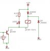
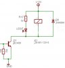
Look at the 2 diagrams below - My basic query is "which one is correct?"


I think that Circuit #2 is correct becuase the circuit #1 will cause osculation of the back-EMF when the relay is turned off becase the current cannot escape to GND (directly) and hence will have to be disapated in the relay coil.

Whereas in Circuit #2, when the relay turns off, the back-EMF is shorted directly to GND.

Can anyone confirm for me please?
 

Attachments

  • image2_170.jpg
    image2_170.jpg
    29.8 KB · Views: 420
  • image3_152.jpg
    image3_152.jpg
    27 KB · Views: 426
Hi Kybert,
Nigel is right.
In circuit #1 when the relay coil's current is suddenly halted by the transistor turning off, the collapsing magnetic field in the coil will generate a reverse voltage across it, but is limited to about 0.7V by the diode. Therefore the collector of the transistor is protected from the very high positive voltage that would occur if the diode wasn't there.
The back-EMF doesn't have to be conducted to ground, it just needs to be reduced in voltage, which the diode across the coil does very well by conducting.

In circuit #2, the back-EMF will cause a very high voltage across the coil, with terminal 1 positive and terminal 2 negative. Since nothing conducts to hold terminal 1 to any reference voltage, current will not flow through either diode. The high voltage may arc across the coil.
 
audioguru said:
Hi Kybert,
Nigel is right.
In circuit #1 when the relay coil's current is suddenly halted by the transistor turning off, the collapsing magnetic field in the coil will generate a reverse voltage across it, but is limited to about 0.7V by the diode. Therefore the collector of the transistor is protected from the very high positive voltage that would occur if the diode wasn't there.
The back-EMF doesn't have to be conducted to ground, it just needs to be reduced in voltage, which the diode across the coil does very well by conducting.

In circuit #2, the back-EMF will cause a very high voltage across the coil, with terminal 1 positive and terminal 2 negative. Since nothing conducts to hold terminal 1 to any reference voltage, current will not flow through either diode. The high voltage may arc across the coil.
I just ran a sim on circuit 2 (for what it's worth). Both ends of the coil fly positive, with a very high voltage damped oscillation on terminal 1. I used a 10mH - 20mH inductor with 50 - 100 ohms of resistance, paralleled by various capacitors in the range of 10pF - 100pF. The interesting thing was that the peak voltage on terminal 2 is apparently held by the capacitor(s), because, in the sim, the voltage on both terminals settles rapidly and holds flat at several hundred volts, the actual value depending on the capacitance, inductance, and resistance of the coil. Not an intuitive result, at least to me.
Of course, most transistor and LED models don't include breakdown voltage, so these values would be clipped, and devices would probably be damaged.
 
Ron H said:
[I just ran a sim on circuit 2 (for what it's worth). Both ends of the coil fly positive, with a very high voltage damped oscillation on terminal 1. I used a 10mH - 20mH inductor with 50 - 100 ohms of resistance, paralleled by various capacitors in the range of 10pF - 100pF. The interesting thing was that the peak voltage on terminal 2 is apparently held by the capacitor(s), because, in the sim, the voltage on both terminals settles rapidly and holds flat at several hundred volts, the actual value depending on the capacitance, inductance, and resistance of the coil. Not an intuitive result, at least to me.
Of course, most transistor and LED models don't include breakdown voltage, so these values would be clipped, and devices would probably be damaged.

But why use two diodes and do it badly?, when you can use one diode and do it correctly!.

Where did you invent the scheme from?, I've never seen anything like it before :lol:
 
I didn't know how to do it correctly...

That's the point of my question, i was trying to firuge out what is happening and what i need to do about it,


Now i know and can move on to my next problem..


Cheers all,

J
 
kybert said:
I didn't know how to do it correctly...

That's the point of my question, i was trying to firuge out what is happening and what i need to do about it,

Steal it from somewhere else :lol:

There are hundreds (if not thousands) of examples on the net, in manufacturers datasheets, in magazines, or in commercial product service manuals. They all use a reverse connected diode across the relay coil - so it seems pretty obvious it's a good idea!.

It's always a good idea to look at other peoples circuits, and try and figure out what they are doing and how they work, it's not as complicated as it sounds - most circuits can be simply broken down in to much smaller modules.
 
Nigel Goodwin said:
Ron H said:
[I just ran a sim on circuit 2 (for what it's worth). Both ends of the coil fly positive, with a very high voltage damped oscillation on terminal 1. I used a 10mH - 20mH inductor with 50 - 100 ohms of resistance, paralleled by various capacitors in the range of 10pF - 100pF. The interesting thing was that the peak voltage on terminal 2 is apparently held by the capacitor(s), because, in the sim, the voltage on both terminals settles rapidly and holds flat at several hundred volts, the actual value depending on the capacitance, inductance, and resistance of the coil. Not an intuitive result, at least to me.
Of course, most transistor and LED models don't include breakdown voltage, so these values would be clipped, and devices would probably be damaged.

But why use two diodes and do it badly?, when you can use one diode and do it correctly!.

Where did you invent the scheme from?, I've never seen anything like it before :lol:
Nigel, I don't know if you intended the questions for me or Kybert. I didn't invent it, I just thought it would be interesting to simulate it. I agree completely that circuit 1 is the correct way to do it.
 
Ron H said:
Nigel, I don't know if you intended the questions for me or Kybert. I didn't invent it, I just thought it would be interesting to simulate it. I agree completely that circuit 1 is the correct way to do it.

Sorry Ron, it was for Kybert, it looks like I left an extra '[' in by mistake :cry:
 
Status
Not open for further replies.

Latest threads

New Articles From Microcontroller Tips

Back
Top