Continue to Site

Welcome to our site!

Electro Tech is an online community (with over 170,000 members) who enjoy talking about and building electronic circuits, projects and gadgets. To participate you need to register. Registration is free. Click here to register now.

  • Welcome to our site! Electro Tech is an online community (with over 170,000 members) who enjoy talking about and building electronic circuits, projects and gadgets. To participate you need to register. Registration is free. Click here to register now.

Which One Is Better

Status
Not open for further replies.

E2K

New Member
Hi All
I want a circuit for emergency Light.
Did some one help me to chose a better circuit for long
lighting time.
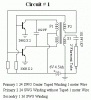
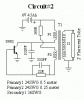
Which one is Better Circuit#1 Or Circuit#2

I also need a circuit for fast battery (6v 4.5Ah)charging
How can i use max712 for this purpose.
 

Attachments

  • Circuit1.GIF
    Circuit1.GIF
    4.8 KB · Views: 3,677
  • Circuit2.GIF
    Circuit2.GIF
    3.5 KB · Views: 1,634
Last edited:
Circuit one is the best, it powes the tube of AC rather than pulsed DC.

Look at the datasheet for the MAX712.

Also note that if you're using a lead acid batter yyou don't need a fancy IC like to charge it, a constant voltage power supply will do.
 
Also D882 is getting hot too much. So it needs an adequate heat sink.

Instead of 2 Feet fluorescent tube you can couple two 7W small fluorescent tubes to get a sharp brightness also considering power consumption.
 
Thanks Buddy

I am using 6.6 V D.C supply circuit for Charging It charge battery too slow nearly (Minimum.3 hours). I want a fast charger that can charge the battery in maximum 1 Hour. Do you have any other Circuit?
 
I second what Gayan Soyza says about using 7W tubes.

Also note that getting good performance from these simple circuits can be a challenge, you might need to play with the resistor values a bit to optimise it.

Charging at 7V will charge the battery faster (6.6V won't charge it fully) but why do you want a fast charger with an emergancy light? Normally you leave the thing pluged in continously so you don't need a fast charger.
 
which one?

No one asked what type of battery do you use.

For lead acid batteries the low current charge voltage would be 6.8V and you can leave it connected forever, the fast charge voltage would be 7.2V but after a full charge you should switch it to lower voltage.

About these designs, I would go for a simpler one or probably make both and see which is more efficient e.g. which would heat less air and give more light.

Also, the second design also gives AC at the secondary.

Good luck,
 
The second design does not give true AC at the secondary, it gives a stream of negitive pulses. If the tube is powered from it for too long only one of the cathodes will turn black dramatically shortening the life of the tube.

I assume he's using a lead acid battery.

The best option for a fast charge would be a microcontrolled charger and there are plenty of circuits around on the Internet for that.
 
so would this happen to be like one of those exit signs they put above doors? As far as i know those things are plugged in all the time. I found one of those down at the dump, I took it home, opened it up and found a nice little 3 volt rechargeable battery. There was only one tube inside it, and a little inverter circuit to power it.
 
Emergency circuits means in sudden situations like power failure's the circuit must react.

I have seen most SLA charger circuits in emergency lights they use overnight charging methods.They have adjusted the charging voltage to 6.8V-6.9V standby voltage as in the battery specifications.
 
to hero999

Sorry, I do not mean to start anything bad here but...

In both designs the uotput current is going to be AC.
Absolutely.

Maybe not the best shape though, but that has to do with an oscillator circuit.

Cheers.
 
panter said:
Sorry, I do not mean to start anything bad here but...

In both designs the uotput current is going to be AC.
Absolutely.

Maybe not the best shape though, but that has to do with an oscillator circuit.

Cheers.
I think we might be getting in to the pulsed DC vs AC debate again.

Alright I'll avoid that one for now.

If you drive a transformer with a single transistor then you'll get pulses of current as the field collapses around the coil; these pulses will always be in the same direction.

The circuit with two transistors is a push pull blocking oscillator; the transistors turn on alternately and the coils are wound out of phase so the field alternates therefore the current in the secondary alternates between positive and negitive.

Of course you can make the first circuit produce true AC by adding a DC blocking capacitor in series with the load but it still won't be as good.

A good analogy is a complementary pair driving a load vs an h-bridge; the complementary pair won't give a true AC waveform without a DC blocking capacitor and the h-bridge will.
 
Hero999 said:
I think we might be getting in to the pulsed DC vs AC debate again.

Alright I'll avoid that one for now.

If you drive a transformer with a single transistor then you'll get pulses of current as the field collapses around the coil; these pulses will always be in the same direction.

The circuit with two transistors is a push pull blocking oscillator; the transistors turn on alternately and the coils are wound out of phase so the field alternates therefore the current in the secondary alternates between positive and negitive.

Of course you can make the first circuit produce true AC by adding a DC blocking capacitor in series with the load but it still won't be as good.

A good analogy is a complementary pair driving a load vs an h-bridge; the complementary pair won't give a true AC waveform without a DC blocking capacitor and the h-bridge will.
You've got me confused. Both circuits have transformer-coupled outputs, so no DC can flow unless the load is nonlinear. Furthermore, the 1st circuit does have a blocking capacitor in series with the load. Perhaps you meant to say "you can make the second circuit produce true AC by adding a DC blocking capacitor in series with the load". As I think you were implying, the 2nd circuit probably produces AC with a non-50% duty cycle.
A complementary driver can produce true AC if the load is returned to GND, while the driver swings plus/minus.
 
let's clarify

Guys,

When I went to university, the EMF in secondary winding (let's make it simpler -Voltage) depended not on absolute magnetic flux but the change in that flux in time. So any DC component in the primary just won't go through the transformer, then you can say that those windings are galvanically isolated. That is actually the second use of a transformer.
Any DC component in the primary wind. will just heat it up, and reduce power handling capacity of the core, which makes a capacitor a good idea. You just need to tune it well to avoid too much oscillation.
This ground connection at the sec. side is there just to prevent voltage buildup due to various parasitic effects, pesonally I'd put a 1K-10K resistor there since actually no current will flow there if the system is built well, and it can preven too quick a discharge while pluging/unpluging the device.

But, again, might be, laws of physics did change, I didn't check lately. :p
 
I didn't say that DC is being transferred from the primary to the secondary side of the transformer.

I just said that without a capacitor in series with the tube circuit 2 will produce negitive pulses rather than both positive and negitive pulses therefore more electrons will be boiled of the negitive cathode of the tube causing it to go black and prematurely fail.

Circuit 1 does have a capacitor in series with the coil and this is to limit the current to the required level and is another reason why it is better than circuit 2.

Here's where I got my information from.
https://www.repairfaq.org/sam/samschem.htm#schlpfi

Although I would agree the author's terminology isn't totally correct, what he says is perfectly valid. I've powered a fluroscent tube of one of these cheap circuits and one end of the tube got dark causing it to fail prematurely.
 
Let's explain the basics here.

Ok, now,

I see why the first design tends to perform better. I'd still check it. Now believe me even if you feed the primary with AC+DC, the only current that you can get on the secondary will be AC, regardless if you drive the core to saturation or not. Of course if you do you'll have some losses there.
Let's see.
As primary gets series of pulses, the core's flux goes from 0 to maximum flux, (not - to + max-flux as if you'd power it with AC, drawback: you can use only half the transfer energy capacity of the core but that's not the issue here) As the flux rises you'll get the EMF in one direction, as it falls to zero, you'll get the emf in other direction. NO DC COMPOUND!
The most probable reasons for blackening one side of the tube (thus emmiting mass of one heater/electrode) would be:
-unbalanced duty factor, The duration of pulse should be as much as just to drive the core to saturation or even better, just not to. Duration of off period should be the same (as to allow the core to recover to zero). This can take some fiddly tuning and adjusting.
-the second reason would be very different rise and fall times of those pulses hence one electrode would handle higher current, the shorter time and vice versa. That can pretty much evaporate the electrode during time.
Otherwise, it should just work fine.
The first design makes beter use of transformer, hence the smaller is needed, but not really a standard one, and is easier to tune. The second uses one transistor, and a bigger transformer, but can be one off a shelf, and is a bit more fiddly to tune. Choose for yourself.
Personally, I would get a Chinese one for almost nothing and probably wouldn't bother too much if not going for a production of it.
 
I think I see what is happening.
The secondary waveform is not symmetrical but has high negative peaks. The tube only conducts when this high peak is present, therefore the tube itself is acting "in a non-linear manner" as a rectifier, conducting only during part of the cycle, producing DC, causing the tube to wear at one end.

Bob
 
It definitely doesn't produce any positive spikes of a high enough voltage to cause the other cathode of a neon lamp to glow for long enough for the eye to see.

I agree the duty cycle is totally off 50% but remember that the power transferred during the positive side of the cycle is the same as the negitive; if not then the transformer will be transferring DC from the primary to the secondary which is impossible,

I think both our thinking is skewed here. What we have both neglected is the flyback effect. Consider a perfect transformer with a 1:1 turns ratio and a primary and secondary inductance of 1H connected to a 1V power supply via a switch; the switch will turn on practically instantly but it takes exactly 1ms to turn off and the current decay is linear. Suppose we turn on the inductor for one second v=di/dt so the secondary voltage will be 1V and during that time current will grow to 1A, now if we turn off the switch the current will decay to zero in 1ms, v = di/dt so the output voltage will decay by 1kV giving an output of -999V for 1ms.

Exactly the same thing is going on in the single transistor inverter, it's only the negitive pulses that are a high enough voltage cause the tube to light; therefore the electrode at the negitive end of the tube gets worn out and not the positive electrode.

Have we reached a consensus on this issue?:D
 
Hero999 said:
<snip>the power transferred during the positive side of the cycle is the same as the negitive; if not then the transformer will be transferring DC from the primary to the secondary which is impossible,<snip>
What about a transformer driving a half wave rectifier?
 
Good point, in that case a transformer can obviously transfer pulses of DC.

There again if you add a rectifier to the output of a transformer running on AC, you'll get a DC current in the primary which will induce an equal DC current in the primary which will normally cause core saturating and over-heating; this is why it should never be done! However, if you're powering the transfromer from a pulsed DC source like a a transistor in common emitter configuration then this would be an issue, I've seen many flyback transformer circuits that have a half wave rectifier on the output.

Nigel,
You are worng in saying that there's no such thing as pulsed DC and that pulsed DC is the same as AC. The output of a rectifier is pulsed DC and the same is true for an oscillator IC with an open collector output.
 
Hero999 said:
Nigel,
You are worng in saying that there's no such thing as pulsed DC and that pulsed DC is the same as AC. The output of a rectifier is pulsed DC and the same is true for an oscillator IC with an open collector output.

I'm not saying there isn't such a thing as 'pulsed DC' - just that it's AC anyway. It goes through a capacitor, it goes through a transformer, the two basic properties of AC.
 
Status
Not open for further replies.

Latest threads

Back
Top