Continue to Site

Welcome to our site!

Electro Tech is an online community (with over 170,000 members) who enjoy talking about and building electronic circuits, projects and gadgets. To participate you need to register. Registration is free. Click here to register now.

  • Welcome to our site! Electro Tech is an online community (with over 170,000 members) who enjoy talking about and building electronic circuits, projects and gadgets. To participate you need to register. Registration is free. Click here to register now.

Which Laminator for 1.6mm pcb (UK)?

Status
Not open for further replies.
Hi,

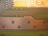
Can anybody recommend a suitable laminator for P 'n' P that will accept a 1.6mm thick pcb. I purchased one of ebay (uk) - a Rexel LP10 but it jams up.

Thanks in advance for any suggestions.
 
Last edited:
Maybe contact these guys and see if they sell a 220V version -


I used to recommend Dynaart, but they seem to have gone out of business.
 
Last edited:
Hi,

Thanks for the suggestion. I think I've see these units on ebay. Not sure they will accept 1.6mm board though. Reading through the page you linked to they seem to use 0.8mm and that's not as easy to obtain (from the suppliers I use anyway).

Thanks.
 
This GBC laminator does both sizes - Digi-Key - 182-1029-ND (Pulsar - 50-1301)
- I assumed it was the same unit, but apparently not. On a positive note, since it is made by the same company and not listed on that page, perhaps they have more items, including an 1.8mm, 220V version, that they sell from a distributor in the UK. Send them some email.
 
Badger,

have you had a peek inside the laminator yet? Maybe you could add some spacers to place the rollers a little further apart, just enough to accept your PCB's.....

If it doesn't look easy initially, post up some pics of the insides and see if anyone can offer a solution.

Regards.
 
Yes, that's exactly how Dynaart made their first fusers. They took a regular fuser, opened it up, stuck a couple of washers in there, then resold it. A screwdriver and ten cents worth of washers may make Angry Badger a Happy Badger.
 
Hi,

Opened up the laminator, the only way to get the pcb through would be to reduce the diameter of the rubber rollers I think. Not sure how that could be done (lathe?). Could slot the holes the bottom rollers are mounted in but that would disengage the drive gears and the board would hit the bottom edge of the heater assembly.

Think I'll nip to Argos tomorrow and get a cheapo clothes iron - give that a go.

**broken link removed**

**broken link removed**

**broken link removed**

**broken link removed**

**broken link removed**

**broken link removed**

**broken link removed**

**broken link removed**
 
Bit of a bummer there...

Ok, a bit of a stab in the dark here, but how hard is the rubber the rollers are made of?

If it is soft enough and you fancy a go at modding to accept PCB's, how about spinning the rollers using a drill (obviously removing the motor/drive gear first) and creating multiple grooves, let's say 1mm deep and 1mm wide in both the top and bottom rollers, leaving another 1mm width inbetween grooves. This may then allow the rubber to compress a little, allowing a PCB to pass through, whilst still preserving the ability to be used as a laminator.

HTH.
 
Hi Mickster,

Interesting idea. The rubber is pretty softish. I suppose the grooves would have to be cut in a 'V' shape to remove the rubber? Would need a lot of grooves though - quite some work! Will think about it a bit more. Thanks.
 
Unless you have used a iron to make PCBs I would put the time into the laminator.

I would try reducing the size of the rollers. Because both rollers are driven you need to reduce then by equal amounts.

If you do not have a lathe you could chuck them into a drill press using a bushing on the bottom.

Try using sand paper on a board to remove material instead of a lathe tool. Measure often.
 
Hi,

Gave up on the laminator idea - for now anyway. Took several attempts to get a decent print with a clothes iron, had to keep the iron on the board for 20mins-ish and had to do some touching up with a pen.

Made some mistakes - ended up with my switches the wrong way around. Poor alignment between the top and bottom layers but I just about managed to 'get away with it'.

Anyway this is the result:

Thanks to everyone who provided assistance with my project, directly or indirectly.
 

Attachments

  • Clock pcb 002.jpg
    Clock pcb 002.jpg
    542.7 KB · Views: 459
  • Clock pcb 012.jpg
    Clock pcb 012.jpg
    497.8 KB · Views: 379
  • Clock pcb 019.jpg
    Clock pcb 019.jpg
    435.3 KB · Views: 361
  • Clock pcb 020.jpg
    Clock pcb 020.jpg
    494.5 KB · Views: 361
  • Clock pcb 021.jpg
    Clock pcb 021.jpg
    492.2 KB · Views: 375
  • Clock pcb 023.jpg
    Clock pcb 023.jpg
    514.5 KB · Views: 378
  • 1.jpg
    1.jpg
    484 KB · Views: 365
  • 13.jpg
    13.jpg
    487.6 KB · Views: 363
  • 14.jpg
    14.jpg
    511 KB · Views: 332
  • 15.jpg
    15.jpg
    507.5 KB · Views: 351
  • Finished Clock 026 r with text.jpg
    Finished Clock 026 r with text.jpg
    556.8 KB · Views: 515
Heres a tip

Print the artwork out on paper first with 3 sacrificial pads/holes in 3 corners of the PCB. Drill these before doing the rest of the developing/ironing/transfer and its easier to get both sides lined up.

Apart from that - its looking good :) I use photoresist and get fantastic results but a lot of people seem to like this press and peel stuff.
 
Frozen Rubber .......

Hi Mickster,

Interesting idea. The rubber is pretty softish. I suppose the grooves would have to be cut in a 'V' shape to remove the rubber? Would need a lot of grooves though - quite some work! Will think about it a bit more. Thanks.

I saw somewhere that after vulcanization they froze the rubber rollers before they ground them to the final diameter.
But I don't remember to what temperature. I guess any temperature low enough to make the rubber hard but not brittle.
 
Status
Not open for further replies.

Latest threads

New Articles From Microcontroller Tips

Back
Top