Continue to Site

Welcome to our site!

Electro Tech is an online community (with over 170,000 members) who enjoy talking about and building electronic circuits, projects and gadgets. To participate you need to register. Registration is free. Click here to register now.

  • Welcome to our site! Electro Tech is an online community (with over 170,000 members) who enjoy talking about and building electronic circuits, projects and gadgets. To participate you need to register. Registration is free. Click here to register now.

Which IC makes the best amplifier?

Status
Not open for further replies.

gary350

Well-Known Member
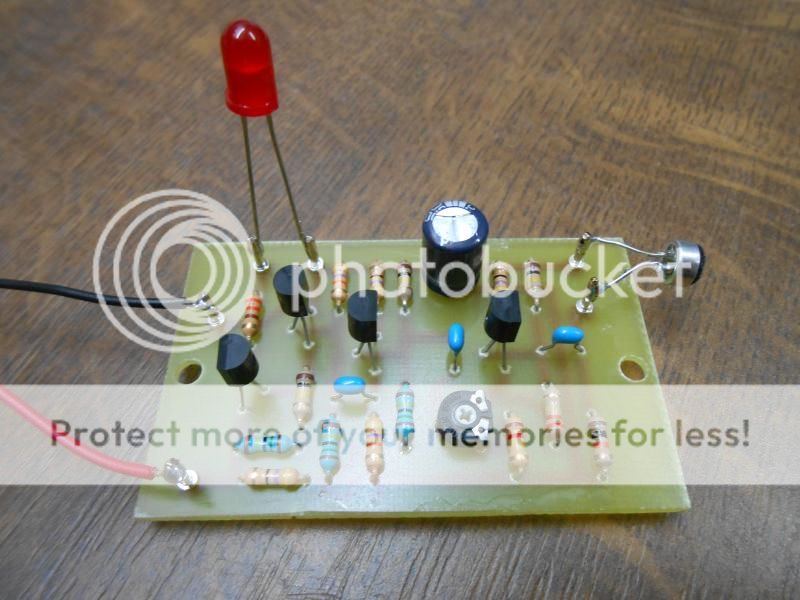
I built his circuit from parts in my junk box. Transistors are general purpose. Not sure what this mic is. I have no clue what the amplification factor is.

I need something smaller with less parts easier to build. Which IC makes the best amplifier?

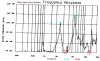
I tried this mic on my frequency meter it does not work without an amp. I am using the mic to pick up frequency from a piano. I hit the keys the mic picks up the sound and my frequency meter tells me the frequency of that key. If the strings are out of tune I can turn the adjustment and the meter tells me when it is in tune. Then I move to a different key. It works excellent.

I have searched ebay for an hour looking for a small PC board solder on mic but nothing comes up. What is the correct name for these small mics? What is the best mic to buy?

I need a good one IC amp and a good mic?

DSCN039111_zps4dda93ca.jpg
 
You're looking for an electret microphone, most have an inbuilt first stage amp. I don't think the frequency response is very good though.

But other people here are better at audio than me
 
I did electret microphone search on ebay. I orderd 10 mic $1.93 free postage from China. I will find out how well they work in about 3 weeks.

I might use an LM386 IC I have used them for other projects. Maybe I should try TL071.
 
You're looking for an electret microphone, most have an inbuilt first stage amp. I don't think the frequency response is very good though.

Actually the frequency response of them is exceptionally good - they don't have an in-built first stage, they have an FET buffer which is required for it to work.
 
Here is the frequency response of a half-decent electret microphone. A cheap one is not much different.
 

Attachments

  • Electret microphone.PNG
    Electret microphone.PNG
    16.8 KB · Views: 331
Attached is a simple non-inverting amplifier based on an op amp.

Your application - the amplification of a signal of fairly high level from an electret microphone - doesn't need a really high performance op amp, so the lowly LM741 should do fine, as would the aforementioned TL071 or TL081. The pin-outs shown are for the single-section op-amps mentioned, but dual-section op amps could be used if the appropriate pins are used for a single section - you'd just leave the unused pins floating - which wouldn't matter in this application.

How it works:

R1 and R2 are equal resistance and form a "virtual ground" at "mid-supply" voltage with C2 filtering out any noise and residual audio. Because the non-inverting input needs a voltage reference, R3 biases it at the same mid-supply - but since there is a little bit of audio that gets back to R1/R2, C2 removes that audio.

R4 and R5 work together to form the feedback circuit to set the gain, with the left side of R4 working against our "ground" (again, C2 is important here as it sets the impedance low at audio frequencies) and the voltage gain of this circuit is:

1 + R5/R4

You can read more about this circuit here: https://en.wikipedia.org/wiki/Operational_amplifier#Non-inverting_amplifier

The values aren't critical at all, except as noted:

R1 = R2 - They must be the same, but they may be anything from 1k to 100k. I'd pick 10k.
R3 - This should be pretty high to prevent loading of the electret microphone so anything from 10k to 100k would be fine. I'd pick 22k-47k.
R4 - This partially depends on the potentiometer that I have around, but you don't want it to be too low. A good range would be 1/20th of the maximum value of R5 or so - or even a higher ratio - let's say, 10k.
R5 - If I had a 100k potentiometer, this would give me a maximum voltage gain of 11 (about 21dB) and if I had a 500k potentiometer this would give me a maximum voltage gain of 51 (about 34dB). It all depends on what you need. I suspect that the 100k will work in your case - but you can always decrease R4 OR increase R5.
R6 - This sets the bias on the electret microphone and the value depends on the microphone itself. If it's an unknown microphone I'd start out with 10k if V+ is 9 volts: You should see 1-5 volts at the junction of R6/C1 when the microphone is operating normally.
C1 - This would effectively set your low frequency response. If you need, say, 100 Hz as the low end, you can get away with something as low as 0.1uF and be just fine - but I'd not go much above 10 uF. (A polarized is shown, but it not need be.)
C2 - This should be large enough in value to bypass audio that might appear. A value of 10uF-100uF is fine - I'd probably use 22uf-47uF.
C3 - This sets the coupling of the output. If it's driving a high-impedance output, 1uF-10-uF is fine and if it's lower impedance, you might need to go as high as 47uF-100uF. I suspect that your application would be OK with something in the 1uF-10uF range.
C4 - This bypasses the power supply. Often, you can get away without this since the batter that one might use has enough bulk capacitance to do the job. I always put at least a 0.1uF there for good measure, but a single 10uF would be fine, particularly if the power source was located some distance away from this circuit as the lead length can cause instability.
V+ - This depends partly on the op amp that you choose. "Officially", the '741 and the TL071, etc. may not be happy with a partially-discharged 9 volt battery, but usually all that happens is that the output gets anemic rather quickly when the voltage drops down. Since are not likely to be needing the full output of the op amp under any circumstances, I suspect that a 9 volt battery would be fine, but anything up to 18-24 volts (assuming that the capacitors' voltage ratings are adequate!) would be suitable for the '741 or the TL071/TL081. If you choose a different op amp, you'll have to check its ratings!

One thing of which one should be aware: With an op amp like the '741, don't expect it to work really well with a voltage gain much above 20-50 or so with a good frequency response - but that's probably not much of a concern in your application.


Best of luck!
 

Attachments

  • audio_amp_1.gif
    audio_amp_1.gif
    5.7 KB · Views: 437
Your application - the amplification of a signal of fairly high level from an electret microphone
WRONG. An electret mic has the same low level output as from a dynamic (coil and magnet) mic. The preamp needs a gain of 50 to 200 times. But if the piano is played loudly and the mic is inside it then the gain can bhe maybe only 10.

- doesn't need a really high performance op amp, so the lowly LM741 should do fine
Why use the antique noisy old 741 opamp when an audio opamp like a TL071 is inexpensive and available?

dual-section op amps could be used if the appropriate pins are used for a single section - you'd just leave the unused pins floating - which wouldn't matter in this application.
It would result in disaster, probably noise and oscillation. an unused opamp should be disabled properly.

The datasheet for the multimeter has no detailed spec's but I think the input impedance for measuring frequency is high. Its frequency calibration is not good at plus or minus 3% and it has only one range so low frequencies will have very few numbers.
 
I can not find any micro small microphones on ebay except for the electret. I would like to have a mic that solders to the circuit board then I don't have to deal with long wires.

What about a small 1" speaker for a microphone. I can use a transformer for impedance matching. No one I know of makes 5000 ohm speakers these days. I have not seen a 5K speaker in 50 years.

I use an 8" 8 ohm speaker for my big ear listing device. I can hear people talking several city blocks away.

What I need is something I can set on or near the piano and watch the meter as I push the keys 1 by 1. If I can hear each tone then the microphone needs to be able to hear it too.

I think your right about the meter it will show only 2 digits. 500 Hz will show up as .50
 
I can not find any micro small microphones on ebay except for the electret. I would like to have a mic that solders to the circuit board then I don't have to deal with long wires.
Radio Shack has one with pins that solders directly on a pcb. Today they wrongly call it a "condenser microphone" but a few years ago they correctly called it an electret mic.

What about a small 1" speaker for a microphone. I can use a transformer for impedance matching. No one I know of makes 5000 ohm speakers these days. I have not seen a 5K speaker in 50 years. I use an 8" 8 ohm speaker for my big ear listing device. I can hear people talking several city blocks away.
A speaker has a strong resonance that makes a "boomy" sound. Also its frequency response is not flat, it is all over the place.
 
I ordered 10 Electret mics from china for $1.93 free postage. They will arrive here in about 3 weeks. When they arrive I see find out how well they work. I hope the Electret mic works with an amplifier with a gain of 20 on my Victor 9805A meter. I think 2 digits on the meter may not be enough I might need to by an Audio Frequency counter. There are lots of frequency counters on ebay but I don't see one for low frequency.

The frequency range of a piano is 27.5 Hz to 4180.01 Hz

This frequency counter says low frequency is 1MHz but it shows 7 digits so maybe 27.1Hz will show up as .0000271 on the meter?????

https://www.ebay.com/itm/1-MHz-1-1-...3?pt=US_Radio_Comm_Meters&hash=item1c454fec8d

**broken link removed**
 
Last edited:
Probably it shows only four digits after decimal point.
Here is low frequency meter, 0.1% + 1 digit accuracy.
**broken link removed**
 
Your multimeter has only one range of frequency measurement up to 200kHz max with three digits.
Then 200kHz is 200k, 20kHz is 20.0K. 2kHz is 2.00k, 2ooHz is 200 and 20 is 20.0 but I do not know how it shows "k". Its accuracy is plus or minus 3% which is not good.
My multimeter has 4 digits and quartz crystal accuracy for measuring frequency.

I began to read about piano tuning in Google Wikipedia. Only one octave is tuned to certain frequencies. Remaining octaves are "stretched" by ear so that harmonics of lower frequencies are musically related to fundamentals of higher frequencies.
 
Why use the antique noisy old 741 opamp when an audio opamp like a TL071 is inexpensive and available?

It would result in disaster, probably noise and oscillation. an unused opamp should be disabled properly.


Since we are talking about an amplifier used only to boost the audio from an electret to drive a tuning meter, a cheap, crappy '741 should be just fine for this application: I take your point about the TL071 being much better - and it should be used if it is already on-hand, but I'd be really skeptical if it were to actually make any difference over the '741. If the '741 is readily available at the store down the street but the '071 is not, then I would certainly go for the '741 if I already had them available - unless I had a need for low noise, low offset, good tempco, high open loop gain - all those things that the '741 isn't good at!

As for the unused sections' pins left floating: I should have qualified it a bit better than saying "...in this application". Since this IS a learning forum, it's worth noting that in a dual op amp, the individual sections' isolations are typically on the order of 70-90dB and even if it did oscillate - which is unlikely since the output and inverting input pins are next to each other in the typical package and the stray capacitance would (probably) prevent it anyway - such a phenomenon would likely go unnoticed, if it were to happen at all. Still, you are right in that it probably isn't a great idea just to leave them floating.

What one of us should have mentioned was what, exactly, to do with an unused section. For an unused section one typically ties the output to the inverting input and then ties the noninverting input to either V+ or V-, as convenient: It probably isn't a good idea to tie both the inverting and noninverting to the same place as this, too, can cause oscillation in some devices, but for most modern devices, wiring it as a unity-gain amplifier is quite safe. Now, the pedants among us would point out that there are exceptions to this (e.g. Norton amps, certain types on which V+ and/or V- is outside the allowable range for an input pin, certain devices that are NOT stable at unity gain, etc.) but those are unlikely to be encountered by most, and if they have gone out of their way to use such a device, they should be reading the data sheet, anyway!

WRONG. An electret mic has the same low level output as from a dynamic (coil and magnet) mic. The preamp needs a gain of 50 to 200 times. But if the piano is played loudly and the mic is inside it then the gain can bhe maybe only 10.

Interesting. I've always found the output of the electret element to be on the order of 10dB+ or so above the raw dynamic mic element. As one who has used both types in communications equipment I've always found it necessary to use a preamplifier with a dynamic microphone if it is being used in lieu of the originally-supplied electret on a piece of equipment - and it wasn't a question of impedance matching, either. Interestingly, condensor/electret type studio microphones seem to have about the same output levels as their dynamic counterparts, but I just attributed this to the former being padded down to match...

Thank you for your insight!
 
I searched for 2 hours this is the only TL071 circuit I can find. There are many circuits for music instruments most are 20 to 70 watts with 100s of parts. This circuit says it only has a Gain of 3 LOL. It uses a Piezo speaker as the pick up instead of a mic. It claims to be very good for music with .1% distortion. Gain of 3 is not much I wonder if my meter can read that? Online data says, TL061, TL071 and TL081 can all be used. Max PS voltage is 18.

**broken link removed**

**broken link removed**

**broken link removed**

**broken link removed**
 
Last edited:
You need a microphone with a flat frequency response to pickup the fundamental frequency of the piano you arte tuning.
1) A piezo mic has many resonances that pickup the harmonics, not the fundamental, and it has nulls that might be the fundamental frequency that you want. You found a low gain circuit that is used to pickup the mechanical vibrations of a drum or from a car engine.
2) A cheap tiny speaker has a strong resonance that will completely mess up the fundamental frequency that you want.

Use an electret mic (they have a very flat frequency response) with a good preamp that has as much gain as you need.

Here are the frequency responses of two typical piezo transducers and a typical electret microphone:
 

Attachments

  • piezo speaker.PNG
    piezo speaker.PNG
    52.6 KB · Views: 221
  • piezo speaker-Murata.PNG
    piezo speaker-Murata.PNG
    24.2 KB · Views: 241
  • Electret microphone.PNG
    Electret microphone.PNG
    16.8 KB · Views: 226
The recent circuit you posted has the piezo wafer glued to the body of a guitar or drum to pickup vibrations, not pickup sounds in the air that you want.
 
If I use an Electret mic on the above TL071 circuit will it have a gain higher than 3?

OR should I be looking for an suitable LM741 circuit?

I decide to buy this frequency counter on ebay I think it will work better than my Victor 9805 meter.

I am using a different browser and it does not find amplifiers circuits like Google does. I searched all day yesterday and did not find much today I use Google again now I am finding lots for circuits again. I did not realize the browser makes such a big difference. I am not finding much details about the gain of the circuits?

**broken link removed**
 
Last edited:
The gain of a non-inverting opamp like the LM741 circuit or the last one you posted is simply the ratio of the negative feedback resistors, plus 1. So the gain of the last circuit you posted is (R5/R3) + 1 which is (220k/100k) +1= 3.2 times with ANY kind of input signal. Since the value of its C2 is much too high at 10uF then the value of R3 can be reduced to 4.7k ohms for a gain of 47.8 times.

My browser is Internet Explorer from Microsoft. It gets Google just fine. If you are in a communist country like China then the government stops browsers from going to Google because they do not want their people to see the freedom that we have. Maybe you tried to look at Google at work and your employer restricts the browser there from looking at Google.
 
Status
Not open for further replies.

Latest threads

New Articles From Microcontroller Tips

Back
Top