Continue to Site

Welcome to our site!

Electro Tech is an online community (with over 170,000 members) who enjoy talking about and building electronic circuits, projects and gadgets. To participate you need to register. Registration is free. Click here to register now.

  • Welcome to our site! Electro Tech is an online community (with over 170,000 members) who enjoy talking about and building electronic circuits, projects and gadgets. To participate you need to register. Registration is free. Click here to register now.

Where to start about Switcher CAD?

Status
Not open for further replies.

rea

New Member
Hi, I downloaded multiSim but have a lot of limitations, the 78Mb that I download, I uninstall it inmediately :D, was a loss of time.

I have been searching and I have that you use eagle, I have first used it (some moments before I where trying switcher cad), then eagle was easy...


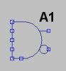
Anyway, I dont know how to use it [EDIT: I dont know how to use Switcher CAD] :S. It dosent have a behaviour like ElectronicWorbench?? (that if I remember OK have the number parts like 7490 and so on....)I say this, because I put a AND gate but have like 4 inputs and one in the down side of the draw with two outputs, if I whant a and gate with only two how I do this?

Also I where not able to run a "thing" that I construct, but I where able to run the examples ;)... they are already constructed.


By the way, I have readed that is more suited for analog design?? than for digital??


Or I can use it instead of worbench almost all the time?

What should I know for use it?
 
Rea you have to type in the name of the part you are looking for , not the number..
click ADD button .. type in AND gate .. no capitals needed..
 
The thing is that Im not able to edit it???
 

Attachments

  • and_184.jpg
    and_184.jpg
    3.2 KB · Views: 436
Yep, Im talking that eagle where easy to draw the diagram and find the component.

Im asking about Switcher CAD, that is a part of that programm ;). I have edited the aprt of the missunderstood, sorry, english is not my natal langauge.
 
Open the help file and search for "logic". This explains how to use the logic parts. The help file is very useful. You will get to know it well when learning to use SwitcherCAD III. I use it a lot, and am very proficient in it. It does not have the "workbench" interface that many of the spice-based simulators have. You need to learn (if you haven't already) how to enter .PARAM, .LIB, .OPTIONS, and several other simulator directives in order to use it.
 
Im reading the help file, I dont know much about this programms (electronic workbench I have only used one time), but what mean this
that accurately exhibits their usual gate charge behavior without using sub-circuits or internal nodes
what are sub-circuits?


By the way, you refer to A. Special Functions.?


to act as 2-, 3-, 4- or 5- input gates with true, inverted, or complementary output. ... . That is, the AND device acts as 12 different types of AND gates.

I understand that thing then I need connect unused inputs to terminal 8 where is the terminal 8?

In the draw I see two outputs, I supose than the top output is the "real" output, but I dont understand they use inverted and complementary like the same word? that will mean 2 words * 4 diferent way = 8 diferent and gates, but in the help file say that if you have 12 = 3*4, that mean that complementary is diferent than inverted????


At the end of that part
The schematic capture aspect of LTspice netlists symbols for these devices in a special manner. All unconnected terminials are automatically connected to terminal 8. Also, if terminal 8 is unconnected, then it is connected to node 0.
I understand, but then when I should "find" the terminal 8.


By the way, I remember I have watched in much places PSPICE, then I need learn it for use switcher CAD???
 
Hi there, I still thinking that "inverted, or complementary" are the same and I can only count 8 diferent and gates, dont know where they take the otehr 4 :).


By the way, I already know where is the terminal 8, also I can open the circuit if I have a doubt for see the name of the pins :D.


I see that I need learn a little spice, but is a nice programm, I where reading a little and doing simple things, one of this is the switch is posible to place one?, also I will like to know if there is a way tou put 7 segment leds or things like that???? or I will need always to watch at the voltage of x diode??


What I do if I whant a 7490 I need to build the component, for example I havent tryied this, but I think is whit the Hierarchy described in the help file???, some one can provide a example???

Where I can find more components?? (only for have fun ;))
 

Attachments

  • 00332.png
    00332.png
    2.3 KB · Views: 369
Below is a schematic of how to implement a switch in SwitcherCAD III. I'm sorry I don't have time to address all your other questions.
Here is the .ASC file, which you can copy and paste into Notepad and save it as a SwitcherCAD III file (filename.asc).

Version 4
SHEET 1 880 680
WIRE -32 320 -32 288
WIRE -32 208 -32 160
WIRE 16 160 16 176
WIRE -48 112 -192 112
WIRE -192 112 -192 144
WIRE -192 256 -192 224
WIRE 32 112 96 112
WIRE 304 176 304 112
WIRE 304 112 288 112
WIRE 304 256 304 320
WIRE 96 112 112 112
WIRE 288 112 240 112
WIRE 112 320 112 240
WIRE 112 176 112 112
WIRE 112 112 160 112
FLAG -32 320 0
FLAG 16 176 0
FLAG -192 256 0
FLAG 304 320 0
FLAG 96 112 A
FLAG 288 112 B
FLAG 112 320 0
SYMBOL voltage -32 192 R0
WINDOW 3 -282 107 Left 0
WINDOW 123 0 0 Left 0
WINDOW 39 0 0 Left 0
SYMATTR InstName V1
SYMATTR Value PULSE(0 5 0 1m 1m 5 10)
SYMBOL sw 48 112 M270
SYMATTR InstName S1
SYMATTR Value mysw
SYMBOL battery -192 128 R0
WINDOW 123 0 0 Left 0
WINDOW 39 0 0 Left 0
SYMATTR InstName V2
SYMATTR Value 12
SYMBOL res 256 96 R90
WINDOW 0 0 56 VBottom 0
WINDOW 3 32 56 VTop 0
SYMATTR InstName R1
SYMATTR Value 1
SYMBOL ind 288 160 R0
SYMATTR InstName L1
SYMATTR Value 1
SYMBOL diode 128 240 R180
WINDOW 0 24 72 Left 0
WINDOW 3 24 0 Left 0
SYMATTR InstName D1
SYMATTR Value 1N4001
TEXT -178 386 Left 0 !.tran 20
TEXT -184 416 Left 0 !.model mysw sw(Ron=1m Roff=1Meg Vt=2.5)
 

Attachments

  • switch_example.gif
    switch_example.gif
    5.4 KB · Views: 364
I see, I have beed playing a little ;).

Version 4
SHEET 1 1316 680
WIRE 1136 64 1136 144
WIRE 656 304 768 304
WIRE 800 304 912 304
WIRE 1136 304 1136 224
WIRE 1024 208 1024 304
WIRE 1024 304 1136 304
WIRE 656 32 656 224
WIRE 672 80 672 144
WIRE 672 144 768 144
WIRE 736 32 1024 32
WIRE 1056 32 1056 64
WIRE 1024 144 1024 32
WIRE 1024 32 1056 32
WIRE 768 304 768 224
WIRE 720 80 912 80
WIRE 912 160 912 304
WIRE 912 304 1024 304
WIRE 768 304 800 304
FLAG 800 304 0
SYMBOL battery 656 208 R0
WINDOW 123 0 0 Left 0
WINDOW 39 0 0 Left 0
SYMATTR InstName V4
SYMATTR Value 15v
SYMBOL res 1040 80 R270
WINDOW 0 32 56 VTop 0
WINDOW 3 0 56 VBottom 0
SYMATTR InstName R6
SYMATTR Value 1
SYMBOL ind 1120 128 R0
SYMATTR InstName L1
SYMATTR Value 1
SYMBOL sw 752 32 M270
SYMATTR InstName S1
SYMATTR Value miSW
SYMBOL battery 768 128 R0
WINDOW 3 -64 66 Left 0
WINDOW 123 0 0 Left 0
WINDOW 39 0 0 Left 0
SYMATTR Value PULSE(0 5 2 999m 12332m 5 30)
SYMATTR InstName V5
SYMBOL cap 1008 144 R0
SYMATTR InstName C2
SYMATTR Value 10µ
SYMBOL battery 912 64 R0
WINDOW 3 -6 51 Left 0
WINDOW 123 0 0 Left 0
WINDOW 39 0 0 Left 0
SYMATTR Value PULSE(0 5 4 999m 12332m 5 30)
SYMATTR InstName V6
TEXT 824 360 Left 0 !.tran 20


I think I need add a sine wave or some thing for turn it off and on???, or this is fine.

Also I have watched some definitions of symbols and I have watched taht they are defined like a subcircuit in a asc file or sub file or even a lib file (7-zip can open if for watch some files).

There are the definitions of the symbols used.... Now I understand if I whant a 7494 I must "write it" I guess. :)


I guess I need practice more, now I understand that for example, I cant put a 7segment display like in ewb, but I can still have a circuit and check the currents there for see if a led is condusing or not :).


A question, in switcher cad for what is only posible to get Volts when I click in the nodes/wires and if I click in a symbol I can only get the current in this symbol (in the graph)
 

Attachments

  • ini1.jpg
    ini1.jpg
    24.7 KB · Views: 353
Status
Not open for further replies.

Latest threads

New Articles From Microcontroller Tips

Back
Top