Electro Tech is an online community (with over 170,000 members) who enjoy talking about and building electronic circuits, projects and gadgets. To participate you need to register. Registration is free. Click here to register now.
Welcome to our site! Electro Tech is an online community (with over 170,000 members) who enjoy talking about and building electronic circuits, projects and gadgets. To participate you need to register. Registration is free. Click here to register now.
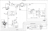
I have assembled a constant current source using an LM317 but the schematic was described as a disaster but why??
It appears to work as planned. R1 in my circuit adjusts the ADC for the RTD temperature sensor.
My as built schematic is the one on the right.
As I understand it I only want 1ma to the RTD to avoid self heating issues.
The circuit as pictured seems to work. Adjusting the pot I get various ADC readings which IMO would indicate the circuit as pictured works.
BUT I was told that the circuit pertaining to the LM317 is a disaster if referring to the data sheet?
I don't want to be able to adjust the current, just the output voltage as it is connected to the RTD/ADC input.
I need more research?
simulated using TINA but?
A constant current source keeps the current constant by adjusting its output voltage up and down.
If you want the output voltage to be constant but adjusted by you then remove the constant current source and replace it with an adjustable voltage reference or adjustable voltage regulator.
I can change the ADC input from -9.74v (RTD=58) to -31.53(RTD=200)
The current varies from -171ma to -171ma at AM1
what am I missing?
I don't have a LM317 to sim but the schematic is supposed to be a CCS.
Maybe the simulation is wrong?
As I understand it I only want 1ma to the RTD to avoid self heating issues.
The circuit as pictured seems to work. Adjusting the pot I get various ADC readings which IMO would indicate the circuit as pictured works.
BUT I was told that the circuit pertaining to the LM317 is a disaster if referring to the data sheet?
It is. The LM317 has a minimum current draw of either 5mA or 10mA depending on which version. You can't set up a design which only draws 1mA or it will not work right.
So in other words I need to use lower resistance on the LM317 output to obtain a draw of 5-10ma. But then need to worry about self heating of the RTD?
Need a better solution? but it seems to work as is but might not be right?
The LM317 was suggested on another forum. I guess I was lead down the wrong path on using the LM317?
Each IC is different. Some LM317 ICs need a minimum load of a couple of mA but the max is 10mA for some of them.
If the load current is not enough for your IC then its output voltage will rise.
Thanks cowboy bob I will give it a try.
As far as appropriate RTD I have no clue as its in a Hakko soldering iron.
At room temp it measures about 58 ohms.
contemplating sticking it in freezer to obtain 0C then maybe graph out a temp curve?
room temp I measure using schematic I posted I get 79mv at RT and 130mv at solder melt which is around 370F.
This I found searching the web. It is in the lm324 data sheet.
The output is very low current .
thinking of using the lm317 as ref voltage of maybe the pic has a ref voltage source (more research).
this circuit is very similar to the one that the Hakko soldering iron uses.
R3 in your current source circuit is supposed to have a constant voltage across it so it can create a constant current. But you have its voltage and current being changed by the pot. So connect R3 directly to the +5V regulated supply instead like this:
Ah yes I see where my mistake was. Wasn't thinking at 11pm last night.
now to figure out a better constant voltage source seeing how the Vcc powering the rest of the circuit may vary some maybe? or just don't worry about it.
now to figure out a better constant voltage source seeing how the Vcc powering the rest of the circuit may vary some maybe? or just don't worry about it.
Could you let us know in what sort of system the RTD is being used as a monitor?
I see that in it's former life, the RTD was used to monitor a soldering iron's temperature. This implies a rather broad hysteresis in control and, as a result, none too tight a requirement for a rock steady power supply for the RTD (not to mention no real concern for current related heating of the RTD).
This site uses cookies to help personalise content, tailor your experience and to keep you logged in if you register.
By continuing to use this site, you are consenting to our use of cookies.