Continue to Site

Welcome to our site!

Electro Tech is an online community (with over 170,000 members) who enjoy talking about and building electronic circuits, projects and gadgets. To participate you need to register. Registration is free. Click here to register now.

  • Welcome to our site! Electro Tech is an online community (with over 170,000 members) who enjoy talking about and building electronic circuits, projects and gadgets. To participate you need to register. Registration is free. Click here to register now.

What the problem is?

Status
Not open for further replies.

epilot

Member
Hello friends,

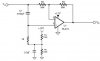
This is a phase shift circuit which I modified to use on a single supply source,
As you can see I used a virtual ground to could use single supply. Even my scope shows that the circuit is working ok specially I can see the amplified signal when I put my finger at the input wire of the op amp, but the circuit does not work with the before circuit that is a small amplifier (single supply 12V too).
The circuit would be pretty
ok if I change the value of R5 to 4.7K.
Does anyone know what the problem is?
 

Attachments

  • 45.JPG
    45.JPG
    11.5 KB · Views: 166
The input is DC-coupled. So if the source signal is 0V then this circuit's output will be saturated against the positive supply voltage.

Add a 0.1uF input coupling capacitor for DC blocking. Then this circuit will have a cutoff frequency of 29Hz.
Add an output coupling capacitor if its DC on the output is a problem to the circuit following it.


The phase-shift is 90 degrees at 34kHz. Is that what you want?
Can your signal source drive a resistance of 1k ohms?
 
audioguru said:
The input is DC-coupled. So if the source signal is 0V then this circuit's output will be saturated against the positive supply voltage.

Add a 0.1uF input coupling capacitor for DC blocking. Then this circuit will have a cutoff frequency of 29Hz.
Add an output coupling capacitor if its DC on the output is a problem to the circuit following it.


The phase-shift is 90 degrees at 34kHz. Is that what you want?
Can your signal source drive a resistance of 1k ohms?


Hi audioguru,

it has a 0.1uF capacitor in series at its input with its before circuit.
Can not see any nistake but it does not work yet,
It seems there is a problem with virtual ground and the before circuit which uses a single supply...

How could you calculate the phase shift and cutoff freq?


what do you mean by this:
Can your signal source drive a resistance of 1k ohms?
 
epilot said:
it has a 0.1uF capacitor in series at its input with its before circuit.
Then it doesn't have a problem with DC to its input. Then its DC output voltage must be 6.0V. Is it?

How could you calculate the phase shift and cutoff freq?
It is called an "allpass filter" and the calculation is in Google: 1 divided by 2 x pi x R x C.

what do you mean
The input impedance of this circuit at high frequencies is only the 1k resistor. many circuits cannot drive an impedance so low.

You haven't said anything about what it doesn't do. You didn't show the circuit feeding it. You didn't say an input level or frequency. You didn't say its output DC and AC levels. You didn;t say what is its load.
 
audioguru said:
Then it doesn't have a problem with DC to its input. Then its DC output voltage must be 6.0V. Is it?

Yes it is 6V


It is called an "allpass filter" and the calculation is in Google: 1 divided by 2 x pi x R x C.


The input impedance of this circuit at high frequencies is only the 1k resistor. many circuits cannot drive an impedance so low.
As you know it is possible to change the 1K resistor with C1(only the negative phase shift will be positive)
I have done that but the circuit did not work. it only works when i use a 4.7K resistor instead of R5.

You haven't said anything about what it doesn't do. You didn't show the circuit feeding it. You didn't say an input level or frequency. You didn't say its output DC and AC levels. You didn;t say what is its load.

Well, at first I want it to change the audio phase between 20uS to 50uS.
the input is a smal single supply amplifier and the output (the next circuit) is an power amplifier(12V single supply).
I can here the amplified signal when I put my finger on the input of the above circuit but when I connect it to the previous it wont work(2 amplifier work ok with each other), then I have to replace the R5 with a 4.7k resistor to have the voice(it is noisy at this state).

the phase shift is variable between 30to 60 degree, so I'll change the 1k resistor to get a multiple angle for multiple speakers.
 
The phase-shift occurs at frequencies far above the frequencies of hearing.
What are you trying to do?

If you change R5 to 4.7k then the input DC voltage to the opamp will be only 0.54V.The opamp input and output can't go down that low and will cause severe distortion.

I think the power amplifier doesn't work when its input is +6V, it needs its input near 0VDC. So a coupling capacitor is needed to its input from this circuit. The input of the power amplifier also might need a resistor to ground.

Post the schematics with part numbers of the small pre-amplifier and the power amplifier and we will be able to see why the whole system doesn't work without anymore of this guessing.
 
audioguru said:
The phase-shift occurs at frequencies far above the frequencies of hearing.
What are you trying to do?

Well I want to phase shift the audio of 7 tiny speakrs(between 20 to 50uS)which are side by side.

If you change R5 to 4.7k then the input DC voltage to the opamp will be only 0.54V.The opamp input and output can't go down that low and will cause severe distortion.

I think the power amplifier doesn't work when its input is +6V, it needs its input near 0VDC. So a coupling capacitor is needed to its input from this circuit. The input of the power amplifier also might need a resistor to ground.

Post the schematics with part numbers of the small pre-amplifier and the power amplifier and we will be able to see why the whole system doesn't work without anymore of this guessing.

there is no schematic at the moment, but the power amplifier is based upon TDA1557 chip(car amplifier). the noly problem I can guess is that the voltage REFRENCE is defirent for the op amp and the previous stage due to the virtual ground on the op amp.
By the way the power amplifier alredy has an input coupling capacitor.
 
Last edited:
Your circuit is much too simple to shift the phase of audio. It shifts the phase only at very high frequencies. Its amount of phase-shift is different at each frequency. A few of these circuits need to be cascaded to have a fixed amount of phase-shift at a few frequencies.

Without seeing a schematic of your combined circuits, I don't know why they don't work.

Are you still trying to transmit a single-sideband ultrasonic signal?
 
audioguru said:
Your circuit is much too simple to shift the phase of audio. It shifts the phase only at very high frequencies. Its amount of phase-shift is different at each frequency. A few of these circuits need to be cascaded to have a fixed amount of phase-shift at a few frequencies.

Without seeing a schematic of your combined circuits, I don't know why they don't work.

Are you still trying to transmit a single-sideband ultrasonic signal?

No, I do'nt want it for high freq.
please be noticed that the phase shift will not be 90 degree and the time delay will be only 50uS MAx, so there is no need for a cascade.
 
Status
Not open for further replies.

New Articles From Microcontroller Tips

Back
Top