amateur_24
Member
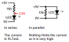
Forgive me for my rusty electronics. The led's I've brought have a voltage drop of 2.5 and takes 25ma of current. Doesn't this mean if I supply it with 4.98V it will blow? I used a led resistor calculator to work out what resistor I needed. My supply voltage is 5.05V (according to my multimeter). Because the avr chips can only sink 20ma of current , I rated the led at 20 instead of 25. It told me that I needed 150ohm but the voltage has barely changed and the current is the same.
I'm only using one led. why hasn't this worked out?
I'm only using one led. why hasn't this worked out?
Last edited: