Continue to Site

Welcome to our site!

Electro Tech is an online community (with over 170,000 members) who enjoy talking about and building electronic circuits, projects and gadgets. To participate you need to register. Registration is free. Click here to register now.

  • Welcome to our site! Electro Tech is an online community (with over 170,000 members) who enjoy talking about and building electronic circuits, projects and gadgets. To participate you need to register. Registration is free. Click here to register now.

What is wrong with this?

Status
Not open for further replies.

ulg

New Member
I know something must be wrong, since really this is one of the first circuits i've designed to utilize semiconductors. But I do like boolean or relay logic so I figure electronics might be productive and interesting.

Let me first say the function is as follows:

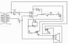
1. Receive 110vac signal from a normally closed sensor.
2. Activate a horn which will shut off after a delay
3. Self reset after 110v signal is off


The values of said components are arbitrary- as I more or less want to know if it would work, and what problems are inherent with it.

I suspect the horn will also chirp from time to time as the capacitor discharges through its resistor and the signal is present.

All feed back (relatively) appreciated ;P
 

Attachments

  • horn_delay.jpg
    horn_delay.jpg
    18.3 KB · Views: 207
Last edited:
R3 and C3 are not connected to anything other than themselves for starters...

The three diodes connected to the transformer what are they doing?
 
Last edited:
I was hoping that R3 and C3 would behave as a inductor parallel to resistance, and the resistor would dissipate charge into heat resetting the state once the signal is removed.

Two of the diodes are for bridging with the third used to take half wave to feed one of the SCR emitters
 
Last edited:
Is this a more appropriate circuit? I should also remember the mantra "Keep it simple stupid" while dipping my toes into a new field lol. So I'm sure anything I post for a while will have a few extra useless things but pointing that out will certainly prevent that in the future lol
 

Attachments

  • Horn_delay_02.jpg
    Horn_delay_02.jpg
    26 KB · Views: 188
Sorry, but you need to go away and study electronics a for a good while yet - like your first effort it just seems to be a random assortment of components connected in a fairly random fashion?.

How are you coming up with these 'circuits', surely you've never seen anything like either of them?.
 
Ok well here is what I was speculating the function would in the last one.

1. On signal from the switch, R1/Pot would energize the inductor while providing +sin AC through that regions SCR and the second SCR facilitates -sin AC.

2. Once the inductor has reached its peak field current would no longer be feeding the gate of the L1 SCR. Then when the signal from the switch is disengaged there would be another short firing but that is pretty inconsequential.

Normally I would do this with relays, but they are pricey

You are showing transistors in the diagrams, NOT SCR's - and the righthand one is wired so as not to work whatever it is.
 
Normally I would do this with relays, but they are pricey
If you know how to do it with relays, use them, all you are doing at the moment is throwing random components ito the air and hoping that they come down connected into the configuration you require.

If in doubt,
make it stout,
using stuff you know about.

JimB
 
Status
Not open for further replies.

Latest threads

Back
Top