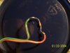
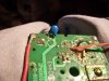
It's the little resistor thing soldered to the red and green wires. It is the only component in a thermostat I'm trying to modify to a different temperature range that changes resistance with temp. At room temp it is ~40K, it drops to ~32K at body temp (closed in my hand). It behaves as a thermistor but doesn't look like one. All the others I find are lollipop shaped. Like the little blue thing in the second pic. which doesn't show continuity or is of infinite Ω. There are no number or other identifiers on it.
While I'm at it, is this all a waste of time? This is an off-the-shelf heat only thermostat from home depot. It's intended for low voltage control of a home furnace. It's range is ~45-90 deg. f. and the resistance of the unidentified thingy is ~40 at 65 deg f. I need a range of ~120-180 deg. f. I'm assuming that if I substitute a thermistor that shows the same resistance of ~40K in the middle of my desired temp range at say 150 and has a similar reaction curve the IC will behave as it does at lower temps. Is that crazy?
Obviously, I'm out of my league when it comes to electronic theory. Any help is greatly appreciated.