Continue to Site

Welcome to our site!

Electro Tech is an online community (with over 170,000 members) who enjoy talking about and building electronic circuits, projects and gadgets. To participate you need to register. Registration is free. Click here to register now.

  • Welcome to our site! Electro Tech is an online community (with over 170,000 members) who enjoy talking about and building electronic circuits, projects and gadgets. To participate you need to register. Registration is free. Click here to register now.

What is this component?

Status
Not open for further replies.

HighPower

New Member
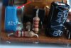
Hi all, this is my first post on the forum. I have a relay controller PCB (that uses a 555 timer) and I am in the process of drawing the circuit diagram for it. The trouble is that I have no idea what the little blue component is. It only has two leads. I'm guessing it could be two components in one. It has 47nS marked on the side of it.

Cheers
 

Attachments

  • UnknownComponent.JPG
    UnknownComponent.JPG
    42.4 KB · Views: 282
hi,
Its a 47nF capacitor

Post the circuit when you have finished drawing it, we can double check.
 
Last edited:
Thanks for your reply. The marking on it is definitely 47nS but I believe you when you say that it is a 47nF capacitor. I have attached the full circuit diagram. Component C6 is the capacitor we are discussing. As you will see, the circuit contains a relay that controls a fuel pump in a car. The design should be such that the relay will only energise if terminal 15 is at 12V and terminal 31b is receiving pulses from the ignition coil. I actually don't understand the circuit if I'm honest.

Can I be cheeky and ask one further question? Can anyone tell from the diagram whether the circuit allows the relay to 'prime' the fuel pump? I mean should the relay energise for a second or two when the circuit is first switched on, whether or not ignition pulses are being received? I imagine there would need to be a capacitor and resistor (CR delay) somewhere to make this happen.

Cheers
 

Attachments

  • Fuel Pump Relay Schematic (original).jpg
    Fuel Pump Relay Schematic (original).jpg
    48.4 KB · Views: 270
Thanks for your reply. The marking on it is definitely 47nS but I believe you when you say that it is a 47nF capacitor.
Cheers

Sometimes, a capacitor only says, for example, 47n, which means 47nF. The S may be a type or some other spec of the capacitor.
 
Re your schematic: There is something wrong with Diodes D3/D4.

C6 is just a power supply bypass so it is not critical at all.
 
Its a clamping circuit, reverse voltage breakdown.
 

Attachments

  • AAesp01.gif
    AAesp01.gif
    12.1 KB · Views: 179
I have tested and measured 1N4148 Vr breakdown on a number of occasions, it's usually about 150v.

That schematic should show D3 as a zener diode I believe, as the voltage on the top of D3 won't get very high at all in operation.

I would also check the resistors around the threshhold and trigger pins on the 555, and the pin labelling. Something looks to be not right on that schematic.
 
Status
Not open for further replies.

Latest threads

New Articles From Microcontroller Tips

Back
Top