Electro Tech is an online community (with over 170,000 members) who enjoy talking about and building electronic circuits, projects and gadgets. To participate you need to register. Registration is free. Click here to register now.
Welcome to our site! Electro Tech is an online community (with over 170,000 members) who enjoy talking about and building electronic circuits, projects and gadgets. To participate you need to register. Registration is free. Click here to register now.
there'll be a short transition phase dependant upon the RC time constant, but at a steady state a cap blocks DC so it'll look like a 5V accross the resistor depending where you take the output. Also if the 5V source passes AC, the arrangment can take care of some noise issues.
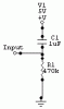
The junction point is connected to input of logic gate.
As DC couldnt cross the cap, the junction of R and C should be at ground level. This is a pull-down circuit, isn't it? Does it make any difference if the capacitor is eliminated from the circuit?
When the power is off, it is at ground level. When it is powered up, capacitor will be charged, at this time, the junction is also at ground level. After DC has become constant, the junction is still 0V. Why is there a delay?
The input will be at 5V when the circuit is first powered on and will decrease to 0V as the cap charges.
Lets call the moment we first apply power t0(time 0). At t0, c1 has no charge. In this state it behaves as a short and has no voltage drop, max current will flow through R1 which will have 5V across it. As the clock ticks on c1 will charge to 5V while the voltage across r1 decreases. Once fully charged c1 will act as an open circuit, no current will flow, and r1 will have no voltage across it.
If you want the input start at 0V and rise to 5V, switch c1 and r1 around.
You have an RC circuit here. The cap won't charge up all at once, the resistor prevents it. The product of R*C will give you the RC time constant (in seconds). A cap is considered fully charged after 5 time constants. So 0.000001*470000=0.47s, 0.47*5=2.35s. It takes about 2.35 seconds for c1 to charge and the input to drop to 0V.
The junction point is connected to input of logic gate.
As DC couldnt cross the cap, the junction of R and C should be at ground level. This is a pull-down circuit, isn't it? Does it make any difference if the capacitor is eliminated from the circuit?
When the power is off, it is at ground level. When it is powered up, capacitor will be charged, at this time, the junction is also at ground level. After DC has become constant, the junction is still 0V. Why is there a delay?
Because you are wrong! - when you power up the circuit the capacitor is DISCHARGED - effectively a short circuit, so it connects the junction of the capacitor and resistor to the +ve rail. As the capacitor slowly charges through the resistor, the voltage at the junction will gradually fall, until it reaches a point where the logic input it feeds decides it's now a LOW rather than a HIGH. The time taken between applying power and this logic LOW condition is the reset time of the circuit.
It's an EXTREMELY common circuit feature, used on microprocessors and many large chips - it's often vital not to start running until the power supply rails have settled properly, the reset delay does this.
The reset pin can be active high or active low, so the capacitor can be at the top or bottom, depending on the reset polarity of the particular device. I've also seen transistors used to invert the reset polarity, presumably to give a higher impedance load for the capacitor?.
Incidently, a PIC has an inbuilt reset delay, so you don't often see this type of reset circuit on PIC's - you can usually just connect MCLR directly to +5V.
When 5V is applied a spike go through the cap (short for AC open for DC). this spike decays at a rate depicted by the resistor.
Thus at power-up the INPUT will be above some logic threshhold virtually straight away. The input will then decay exponentally (as the cap charges up and becomes open-circuit), thus some time later it will cross the lower logic threshold and thus changing the state of that logic chip.
That cct coupled with a 74HC14 schmitt inverter is used alot for power-on resets, and other arroangements of said cct for pulse delaying and pulse stretching.
.....That cct coupled with a 74HC14 schmitt inverter is used alot for power-on resets, and other arroangements of said cct for pulse delaying and pulse stretching.
This site uses cookies to help personalise content, tailor your experience and to keep you logged in if you register.
By continuing to use this site, you are consenting to our use of cookies.