Electro Tech is an online community (with over 170,000 members) who enjoy talking about and building electronic circuits, projects and gadgets. To participate you need to register. Registration is free. Click here to register now.
Welcome to our site! Electro Tech is an online community (with over 170,000 members) who enjoy talking about and building electronic circuits, projects and gadgets. To participate you need to register. Registration is free. Click here to register now.
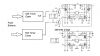
It depends on what the source impedance is of the voltage to the supply (at the top of Q3 and Q5). If it is high, then when the FETs switch on there will be a dip on the rail (proportional to the source impedance x current taken by the motor). If it is low then the dip will be less. The caps hold up the rail. They might not be big enough if the source impedance is high or the current is high (or both)
You belong to the Madman Muntz school of design. Muntz made cheap TVs in the early days of TV. The story was that he would clip out components on a working TV and if it still worked, he would remove that part from production because it obviously wasn't needed.
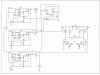
But removing decoupling capacitors is risky. It may work with a specific layout or wire length, but a slight change (even moving a wire) could lead to erratic circuit operation or oscillations (which are sometimes hard to detect). Rule number one in any circuit layout is to use plenty of decoupling capacitors. So there's no good reason to try to save a few cents by leaving them out. It's just bad design practice.
hey the 4th and 5th pin are both attached i just neglected to include it in the schematic. Its to control a Leadscrew type extention where a certain about of time corresponds to a certain extension of the drive shaft.
are there any further errors u might have seen that you'd care to share with me ?
hey the 4th and 5th pin are both attached i just neglected to include it in the schematic. Its to control a Leadscrew type extention where a certain about of time corresponds to a certain extension of the drive shaft.
are there any further errors u might have seen that you'd care to share with me ?
This site uses cookies to help personalise content, tailor your experience and to keep you logged in if you register.
By continuing to use this site, you are consenting to our use of cookies.

 ?
?