sparks_vfr
New Member
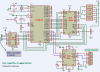
I have attached a circuit diagram that I am going to attempt to re-create...
I do not want to control anything so will not be using U3
My problem is, the symbol for C3 is not something I have seen before (I have not seen that many circuit diagrams)
Is it a polarised Cap ? That I believe is supposed to be shown as **broken link removed**
I would also like to monitor 16 analog devices, would I be able to use an AD7490 as a direct replacement for the ADC0808 ??**broken link removed**
Sparks