Continue to Site

Welcome to our site!

Electro Tech is an online community (with over 170,000 members) who enjoy talking about and building electronic circuits, projects and gadgets. To participate you need to register. Registration is free. Click here to register now.

  • Welcome to our site! Electro Tech is an online community (with over 170,000 members) who enjoy talking about and building electronic circuits, projects and gadgets. To participate you need to register. Registration is free. Click here to register now.

what is it?

Status
Not open for further replies.

fuel__2001

New Member
Hi all

This is my first post and im not the most knowledgable guy when it comes to electronics, so please take it easy on me ;)

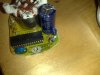
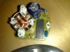
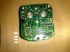
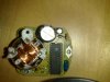
Ive been trying to repair this rev counter from my motorcycle for some time. I finally managed to get the thing to work by replacing 2 capacitors, zener diode and a resistor, all on the right in the picture.

What is bugging me though is the rev counter needle isnt as responsive as an identical rev counter that still has all the orignal parts. The one ive repaired seems to have some sort of lag.

I havent any idea what is causing this needle lag and as a last resort i was trying to find out what component the thing ive highlighted in red is? It has 3 legs and no markings anywhere?

If anyone has any suggestions about the lag or what the mystery part is i would be very grateful.

TIA
 

Attachments

  • edit.JPG
    edit.JPG
    504.5 KB · Views: 267
The big chip is likely a u-controller and the circled thing is a ceramic resonator used to control the frequency of the clock that the u-controller bases all of its timing on. If that part was bad, likely the entire thing would do nothing at all.
 
That item is most likely a ceramic resonator. It is the component that determines the frequency of oscillation of the clock in this digital circuit. These resonators are not easily broken and don't usually drift all that much, so if the counter is working at all, I would not suspect this part as being faulty.

You mentioned that you replaced some other parts including a capacitor. I wonder if you have put too large a capacitor in and this is causing delays in changes to the input signal. And on further thought, it is possible that too large a resistance might cause trouble too. Did you replace with identical values?
 
Last edited:
That item is most likely a ceramic resonator. It is the component that determines the frequency of oscillation of the clock in this digital circuit. These resonators are not easily broken and don't usually drift all that much, so if the counter is working at all, I would not suspect this part as being faulty.

You mentioned that you replaced some other parts including a capacitor. I wonder if you have put too large a capacitor in and this is causing delays in changes to the input signal. And on further thought, it is possible that too large a resistance might cause trouble too. Did you replace with identical values?

Thanks for your reply's.

I swapped all components with what i believed to be exactly the same as what was originally there. I did manage to get hold of another unit to compare components. Other than struggling to identify the orignal zener diode, both the capacitors and resistor i replaced were of identical value.

The reason the rev counter got fried in the first place was a failure of a regulator/rectifier that shouldve been producing a charge of 13.8v-14.4v When the RR failed the charge produced wouldve been high, as the 30ohm resistor was physically burnt out, and later i found the zener to be unservicable too. Which led me to change the capacitors as the needle was still lagging.
 
Last edited:
Some thoughts.

1) I verified that your negative leg is correctly connected on the electrolytic capacitors in the picture, so good going there.
2) Difficult to see your diode and be certain of its bias. Are you certain the black cathode band is in the same direction it originally was? That would unlikely be the problem as you say it functions though with a lag, but make sure it is the same.
3) Do you still have the original components? Perhaps you could snap a photo of them so we can be sure the replacement components are in fact identical. I'm sure you have it right but we are all human.
4) The DIP IC is obviously functional, but we don't know the assignment of every pin and a partial failure could have occurred when the regulator failed...ICs have internal resistors, diodes, transistors that can conceivably function with one internal component faulty. Also, I can't see the ID for the chip. Perhaps you could offer the numbers printed on it and we can pull a datasheet. It might be a uC or OEM device but it might be a standard package too.

It is a pretty small circuit. Reverse engineering these is always helpful. That is if you can draw schematics. Backside photographs might help too.
 
Some thoughts.

2) Difficult to see your diode and be certain of its bias. Are you certain the black cathode band is in the same direction it originally was? That would unlikely be the problem as you say it functions though with a lag, but make sure it is the same.
3) Do you still have the original components? Perhaps you could snap a photo of them so we can be sure the replacement components are in fact identical. I'm sure you have it right but we are all human.
4) The DIP IC is obviously functional, but we don't know the assignment of every pin and a partial failure could have occurred when the regulator failed...ICs have internal resistors, diodes, transistors that can conceivably function with one internal component faulty. Also, I can't see the ID for the chip. Perhaps you could offer the numbers printed on it and we can pull a datasheet. It might be a uC or OEM device but it might be a standard package too.

It is a pretty small circuit. Reverse engineering these is always helpful. That is if you can draw schematics. Backside photographs might help too.

Heres some more pictures, hopefully you can see the chip ID and the diode bias. There also a picture of the backside of the pcb.
I will try and get a picture of the original too, just to make sure it isnt user error with the components ive already got on there. Dont rule it out ;)

On on the limits of my soldering ability too, ive got no chance of soldering a chip, although i would give it a go as ive got nothing to lose and im sure the practice would do me good.

Also how would you work out the value of the ceramic resonator if theres no ID on the part?

Thanks for your help, much appreciated.
 

Attachments

  • 13122009277.jpg
    13122009277.jpg
    596.2 KB · Views: 567
  • 13122009278.jpg
    13122009278.jpg
    745 KB · Views: 200
  • 13122009282.jpg
    13122009282.jpg
    893 KB · Views: 207
looking at the underside of the pcb there seems to be a poorly soldered join directly to the left of a 22k surface mount resistor which needs desoldering and resoldering again....also on the underside of the board where its marked R10 there is some more poorly soldered joints....if you have access to an oscilloscope or frequency counter it would give you a good idea as to what frequency that unmarked item is oscillating at.......
 
Last edited:
looking at the underside of the pcb there seems to be a poorly soldered join directly to the left of a 22k surface mount resistor which needs desoldering and resoldering again....also on the underside of the board where its marked R10 there is some more poorly soldered joints....if you have access to an oscilloscope or frequency counter it would give you a good idea as to what frequency that unmarked item is oscillating at.......

Point taken, i will give it a go tomorrow to clean the joins up and get hold of a magnifying glass to make things a little easier. Ive also highlighted the area and the components i soldered on.

It still leaves the question of the lag of the needle.
 

Attachments

  • back soldering.JPG
    back soldering.JPG
    666.9 KB · Views: 179
Just taking a shot at the IC, I didn't turn up a datasheet...though I did find a "similarly" I.D'd uController from another manufacturer. The NS on the chip is the same logo on the Nippon Seiki website (not surprising)...indicating that this is likely OEM/proprietary and a datasheet won't be forthcoming. The significance of this is that reverse engineering and really knowing whats going on with the circuit is not going to be "doable" without a lot more expertise than I possess :)
It probably is a programmed uController unfortunately.

But that is unimportant. You have a lot more going on with the circuit even beyond that. You have a good amount of SMDs which look like resistors, diodes, and transistors. If a regulator failed any of them could have been damaged. With a scope, board connected "in circuit", with the right input and output transducers and signals being generated...you MIGHT be able to find an open circuit with some waveform and voltage checks and ID a failure.

...More trouble than its worth IMHO. I'd get a new board and fuggetaboutit if you can't live with the lag. But that's just one man's opinion. :eek:


Oh....but I would add. A couple of those SMDs look like capacitors. A change in response (a lag) would seem to indicate a reactive element not behaving. A capacitor would qualify. An SMD capacitor might be especially vulnerable to a regulator failure. If I went any further with this I would replace at least the SMD caps.

Yeah...C2 thru C6 appear to be for coupling or noise filtering at the IC inputs. Some associated resistors as well in there. You also have some kind of diode (D1 I think?) on the backside that might need to be checked. And cleaning up the solder joints might set things right as well for sure. Be careful with soldering damaged or potentially damaged thru-hole components. Pieces of trace can be lifted. There are techniques like scraping the lamination off of foil trace and soldering the part to the trace when damage like this occurs.
 
Last edited:
I could be completely wrong, but here's my theory. I think that the small capacitor is for filtering the speed signal. Not the pulses coming from the ignition system, but the voltage proportional to the revs.

Electrolytic capacitors like that get less capacitance with age and have very wide tolerances. It could be that the one you fitted had a much larger value than those on the rev counters you are comparing it with, even though they have the same numbers written on them.

You could try running without a capacitor there at all, which might make the needle vibrate, especially at tick over. Or just try half the value.
 
your picture looks like your soldering might have pervaded some flux to the sides.... I don't know. Just to be sure, I'd wash that PCB coz the flux has some minimal effects on the circuit parameters. Just wash the underside with some suds and scrub 'em using a weathered toothbrush or something, let it dry, and try again.
Just suggesting, it might or mightn't help.
 
Hi Folks ,
This is Jeyruse, I have finished my studies this
year itself. I am staying in Sydney. Glad to introduce myself
in this site. And pleased to meet all the other members
of this site.
 
Why did you put an 18v zener in?? That's the primary (and only regulator). It was most likely a logic level regulator like a 5.1v zener although a lot of those sin/cos tacho movements run from about 8v or so.

You can clearly see the power in path (bottom PCB), from the +12v terminal (top left) through D1 then fuse F1 then to the small 50v cap (regulator Vin cap), then resistor and zener, finally into the large cap (regulator Vout cap).

The signal path from the terminal (top right) goes through a few small parts J12 C4 etc and goes direct into the IC so the IC is measuring time period and not anything analog that you might have affected.

I suggest if you have a working unit to measure the voltage across the zener diode when the tacho is powered up to 12v.

I've seen this type of simple zener regulator in hundreds of automotive devices and NEVER seen an 18v zener used!
 
Why did you put an 18v zener in??

I suggest if you have a working unit to measure the voltage across the zener diode when the tacho is powered up to 12v.

I've seen this type of simple zener regulator in hundreds of automotive devices and NEVER seen an 18v zener used!

Initially i gave the device to someone else to repair and noticed they had used a 6.2v zener. They managed to get the device working, however the needle still lagged but it also started to leave scorch/bubbling marks on the 30ohm resistor.
I managed to get hold of another device and the code on the component was Z184, although this componenet looked nothing like the zener's i had been using.

The 18v zener has stopped the scorching of the 30ohm resistor although the needle still lags.

Once i get on my feet (suffering from a motorcycle crash) i will get out to the bike and run some test on the original device across the zener, and i will upload a picture of the original device, so the original component/zener can be ID'd.

Once again thanks for your input, its a steep learning curve for me :)
 
Last edited:
Update

For those that are follwing this thread here is a picture of the original diode im trying to ID. The only markings on it i can see are Z18A.

Ive still got to get out to the bike to test the diode
 

Attachments

  • 16122009289.jpg
    16122009289.jpg
    852.3 KB · Views: 190
I suggest if you have a working unit to measure the voltage across the zener diode when the tacho is powered up to 12v.

Update - finally got round to putting a working tacho on the bike and the voltage across the zener diode was 12.9v with the engine ticking over.

Is this enough information to work out what the correct voltage of the zener should be?
 
Last edited:
I'm just curious as to why Diode D3 is mising from the board. Is that factory?
 
Sounds like it might be a 18v zener... I would take it out and test it, run 5mA through it and measure its voltage.

If so that's pretty rare, it means the microprocessor is rated for unreg 15v. I've opened a ton of automotive gauges and never seen that before. :eek:
 
I would take it out and test it, run 5mA through it and measure its voltage.

Unfortunately i haven't got a way to test it by putting through 5mA.
If in theory i have put the correct voltage zener onto the board. Would the wattage of the zener, currently 0.5w on the ones Ive replace, have have any correlation to the lag of the needle. Its the lag which has been the problem all along, as I'm running out of ideas really.

AllVol said:
I'm just curious as to why Diode D3 is mising from the board. Is that factory?
Yeah its factory
 
All you need to test it is a variable power supply 0v-20v or so and a resistor (100 ohm is fine) and a voltmeter;

1. Connect the zener diode reversed, in series with the 100 ohm resistor.
2. Slowly turn up the PSU voltage until the voltage across the resistor is 0.5v (100 ohms = 5mA)
3. Now measure the voltage across the zener diode pins

IF it really is a 18v zener is is not a regulator, it's just a spike suppressor so it will dissipate almost no power in normal use. So a 1W or 0.5W etc would not matter a great deal.

The lag of the needle is a weird fault to diagnose because the micro generates sin/cos voltages which turn the needle to the correct angle. So the micro might be faulty. The other parts in the circuit are easy to diagnose being mainly caps and resistors, so you can just lift one leg and use a resitance or capacitance meter.

Also, since you have a working unit, you could connect both side by side to the same 12v DC supply, and start writing down comparison of the voltages on each unit, ie voltage for each micro pin etc etc.

Do you know what blew the original diode, and how did it fail, ie shorted? burnt? cracked open? etc etc.
 
Status
Not open for further replies.

Latest threads

Back
Top