Continue to Site

Welcome to our site!

Electro Tech is an online community (with over 170,000 members) who enjoy talking about and building electronic circuits, projects and gadgets. To participate you need to register. Registration is free. Click here to register now.

  • Welcome to our site! Electro Tech is an online community (with over 170,000 members) who enjoy talking about and building electronic circuits, projects and gadgets. To participate you need to register. Registration is free. Click here to register now.

What is an Opto Pair?

Status
Not open for further replies.
t_anjan said:
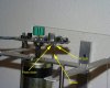
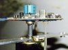
Does anyone have any idea what an opto pair is? I am trying to build a Propeller clock and there is a reference made to an opto pair. Any suggestions?

Thank You for any useful info.

for more info: http://www.metricmind.com/clock/clock.htm
See below. Also see the two pictures in the project named "sensor.jpg" and "sensor2.jpg". And do a Google search for "opto pair".
 

Attachments

  • schem_209.gif
    schem_209.gif
    25 KB · Views: 1,242
It is a coupling method, I don't know the details really, but when the IR LED is on, the photodiode lets current through, and vica versa. It is sort of acting like a transistor.

I can't tell you why it is used there because I don't know :lol:

I believe the method is called opto coupling.
 
Thank you all

Thank You zachtheterrible, Ron H and Sebi for the immediate reply.

Ron H: I know which part of the circuit is the opto pair. I have worked with IR emitters and detectors. I have also googled for "opto pair" (and other combinations) in vain. Iam getting more "opto couplers" in the results, which I am quite sure is not an opto pair, judging by context.

But I am not sure if an opto pair is as simple as an IR Emitter-detector pair. In the actual physical form of the circuit, the emitter is supposed to be stationary and detector is supposed to be on the rotor of a motor. (The detector is supposed to pick up the IR every time it crosses over the emitter while rotating.) This requires a separate supply for the emitter as it is not possible to take out a wire from the rotating part of the design (where the source is). But this is not specifically mentioned in the circuit. That is why I thought that maybe an opto pair is not a simple IR emitter-detector pair, but it may be something that has both the IR emitter and detector facing each other in the same housing, where the emitter sends out pulses at specified intervals. (Something like the OPB706 which is actually an Opto-reflector.) In this way, the emitter and detector can be mounted on the motor, so one supply would be enuf.

I hope I am not boring you all with my long post. But I would be really grateful if someone could give me some ideas....
Thank You
 
Re: Thank you all

t_anjan said:
Thank You zachtheterrible, Ron H and Sebi for the immediate reply.

Ron H: I know which part of the circuit is the opto pair. I have worked with IR emitters and detectors. I have also googled for "opto pair" (and other combinations) in vain. Iam getting more "opto couplers" in the results, which I am quite sure is not an opto pair, judging by context.

But I am not sure if an opto pair is as simple as an IR Emitter-detector pair. In the actual physical form of the circuit, the emitter is supposed to be stationary and detector is supposed to be on the rotor of a motor. (The detector is supposed to pick up the IR every time it crosses over the emitter while rotating.) This requires a separate supply for the emitter as it is not possible to take out a wire from the rotating part of the design (where the source is). But this is not specifically mentioned in the circuit. That is why I thought that maybe an opto pair is not a simple IR emitter-detector pair, but it may be something that has both the IR emitter and detector facing each other in the same housing, where the emitter sends out pulses at specified intervals. (Something like the OPB706 which is actually an Opto-reflector.) In this way, the emitter and detector can be mounted on the motor, so one supply would be enuf.

I hope I am not boring you all with my long post. But I would be really grateful if someone could give me some ideas....
Thank You
Both parts rotate together. Every time they go past the stationary shutter (see below), it breaks the beam between them, creating a synchronizing pulse at the collector of the NPN transistor.
You can buy optical interrupters (search) that have both parts encapsulated in the same assembly.
 

Attachments

  • sensor2.jpg
    sensor2.jpg
    47.5 KB · Views: 1,019
  • sensor_212.jpg
    sensor_212.jpg
    15.3 KB · Views: 1,035
hi,

they are also name opto-isolator, because they can be used as a solid state relay, letting 2 parts communicate without being realy connected, check this page to see what i mean:

**broken link removed**
 
Got it!

Thank you, all of you. Now I have got a clear idea of how the desgin works. Will let you all know how it goes after building it.
 
ikalogic said:
hi,

they are also name opto-isolator, because they can be used as a solid state relay, letting 2 parts communicate without being realy connected, check this page to see what i mean:

**broken link removed**
An optoisolator is generally sealed, and does not allow for mechanical interruption of the light, which is what t_anjan needs.
 
Ron H said:
An optoisolator is generally sealed, and does not allow for mechanical interruption of the light, which is what t_anjan needs.

Exactly......i thought the same thing...
 
Status
Not open for further replies.

Latest threads

New Articles From Microcontroller Tips

Back
Top