Continue to Site

Welcome to our site!

Electro Tech is an online community (with over 170,000 members) who enjoy talking about and building electronic circuits, projects and gadgets. To participate you need to register. Registration is free. Click here to register now.

  • Welcome to our site! Electro Tech is an online community (with over 170,000 members) who enjoy talking about and building electronic circuits, projects and gadgets. To participate you need to register. Registration is free. Click here to register now.

What is a decoupled capacitor?

Status
Not open for further replies.

dar2525

New Member
I am confused and keep seeing the term "decoupled capacitor" tossed around. How are these capcitor used in circuits? Does it remove DC?

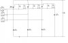
I asked becaused, I have a circuit with 10nf capacitor and 100ohms in series with each other connected to the gate of a silicon controlled rectifier (SCR). I want to know the purpose of this. The AC sine wave is inputted into the circuit.

Any help would be great.
 
The purpose of a capacitor is not to remove DC. DC does not pass through a capacitor, only AC. The purpose of such capacitors is to remove undesireable AC (noise) from the circuit. The value of the caps you mentioned is such as to remove unwanted frequencies from the input of an IC.

Decoupling: To reduce or eliminate the coupling of (one circuit or part to another).
Coupling: Transfer of energy from one circuit to another
 
In this case it is used to provide a pulse of charge of relevant size and the appropriate time to fire the Thyristor.

In this case it really isnt a decoupling capacitor
 
in some cases, a resistor and a capacitor connected in series makes a clock source, but not a clock itself. These two components alone, when their values are multiplied will insert a delay into the circuit. It may not necessarily be a start-up delay, but it is a delay in an electrical sense.

Maybe the author of the circuit is trying to incorporate some delay in feeding the voltage to the SCR.

What exactly does this circuit do?
 
heathtech said:
Decoupling: To reduce or eliminate the coupling of (one circuit or part to another).
Coupling: Transfer of energy from one circuit to another

Thanks for replying. Can you give a short example of the above statement or try to explain more detailed?

Thanks
 
Styx said:
appropriate time to fire the Thyristor.

Thanks for replying. What do you mean by "appropriate time to fire the Thyristor?" Dooes the series capacitor and resistor cause a RC time constant for firing the Thyristor? Can you explain a little further in detail please?
 
mstechca said:
in some cases, a resistor and a capacitor connected in series makes a clock source, but not a clock itself. These two components alone, when their values are multiplied will insert a delay into the circuit. It may not necessarily be a start-up delay, but it is a delay in an electrical sense.

Maybe the author of the circuit is trying to incorporate some delay in feeding the voltage to the SCR.

What exactly does this circuit do?

This is a power managment circuit for controlling how much power is delivered to the load 1kohms. Here is how the circuit actual looks. I do understand the need for R5, R1 and C1. I believe R5 limits the small current flow from triggering the SCR until the positive peak of the input reaches a certain amplitude. I think. help me out. Thanks

The 3 phase voltages are suppose to be 30Vpp
 

Attachments

  • circuit_330.jpg
    circuit_330.jpg
    34 KB · Views: 497
heathtech wrote:

Decoupling: To reduce or eliminate the coupling of (one circuit or part to another).
Coupling: Transfer of energy from one circuit to another

dar2525: Thanks for replying. Can you give a short example of the above statement or try to explain more detailed?

Well, you are being schooled on clock pulsing and other topics by other posters as to the specifics of your circuit, but, I THINK the best way to say it is, as far as decoupling goes : If you decouple something, you detach it, right? Like, if you have two pieces of pipe, you can couple them together with a union, and decouple them by removing the union.
...So, in electronics, circuits can be coupled and decoupled as well. I am not the best at explaining, so bare with me. If a capacitor is put from an input pin of a solid state device to ground, it is "decoupling" the IC or transistor from unwanted noise. Caps PASS Ac, and reject DC, so unwanted AC will go to ground. Depending on the VALUE of the Cap, desirable AC wil not go to ground, and allowed to go to the input of the device. This is called "band-passing", good frequency bands are rejected from ground and "passed" to the input and bad ones are pulled to ground. remember, caps only pass AC.
...Coupling capacitors work the opposite way, they are installed between two components and couple them just as the pipes are coupled with a union. They "promote" the passing of good AC signals, and stop DC from going to device inputs. The DC is rejected, and pulled to ground by either a resistor or choke.
I hope I've explained this OK, maybe someone elso could elaborate or edit my explanation ?
 
heathtech said:
heathtech wrote:

Decoupling: To reduce or eliminate the coupling of (one circuit or part to another).
Coupling: Transfer of energy from one circuit to another

dar2525: Thanks for replying. Can you give a short example of the above statement or try to explain more detailed?

Well, you are being schooled on clock pulsing and other topics by other posters as to the specifics of your circuit, but, I THINK the best way to say it is, as far as decoupling goes : If you decouple something, you detach it, right? Like, if you have two pieces of pipe, you can couple them together with a union, and decouple them by removing the union.
...So, in electronics, circuits can be coupled and decoupled as well. I am not the best at explaining, so bare with me. If a capacitor is put from an input pin of a solid state device to ground, it is "decoupling" the IC or transistor from unwanted noise. Caps PASS Ac, and reject DC, so unwanted AC will go to ground. Depending on the VALUE of the Cap, desirable AC wil not go to ground, and allowed to go to the input of the device. This is called "band-passing", good frequency bands are rejected from ground and "passed" to the input and bad ones are pulled to ground. remember, caps only pass AC.
...Coupling capacitors work the opposite way, they are installed between two components and couple them just as the pipes are coupled with a union. They "promote" the passing of good AC signals, and stop DC from going to device inputs. The DC is rejected, and pulled to ground by either a resistor or choke.
I hope I've explained this OK, maybe someone elso could elaborate or edit my explanation ?

Thanks for the explanation: it is becoming clear. I will analyze futher.
 
Status
Not open for further replies.

New Articles From Microcontroller Tips

Back
Top