Electro Tech is an online community (with over 170,000 members) who enjoy talking about and building electronic circuits, projects and gadgets. To participate you need to register. Registration is free. Click here to register now.
Welcome to our site! Electro Tech is an online community (with over 170,000 members) who enjoy talking about and building electronic circuits, projects and gadgets. To participate you need to register. Registration is free. Click here to register now.
You would like the choke to have a high impedance at 60kHz, and a minimal voltage drop due to its resistance at 30Adc.
X = 2*∏*f* L or L = X/( 2*∏*f)
Say you would like 10KΩ impedance at 60000Hz, L =10000/(2*6.28*60000) = 26.5mH
That would be a huge choke if it where just a coil in air. I tried some values in this calculator, and to get anything approaching 26mH, the DC resistance of the wire will not pass 30A.
It is going to be tough to find a ferrite core that won't saturate with 30A flowing in the inductor. **broken link removed**, but they are special order, and look at the cost.
To calculate a size of the choke you need to know the amplitude of the 60kHz and how much attenuation you need i.e. what voltage value of 60kHz in the power supply voltage can be tolerated.
It is one thing to use Large Filter Caps and Choke to Smooth out the DC, But to help Eliminate RF in the Supply, Also Bypass the Large filter caps with some 0.1 uF Mylar Caps to help attentuate the RF.
Low Value Caps are Better for High Frequency.
Sounds like this is for your induction heater. You might be able to use another microwave transformer core and wind some turns on it, but you should buy a meter to measure it. As you can see from the above formula the lower you make the frequency of the heater the larger the inductor.
If you have one running you should measure the current by adding a small resistor in series with the inductor so we have an idea of the current involved.
You need a coil which has a high impedance compared with the circuit you are trying to decouple.
I just had a quick look back through previous posts about this induction heater and cannot see the information we need. (It may be there, I just did not see it).
First, find the impedance of the circuit.
The usual way to do this for an RF transmitter is to divide the amplifier anode/collector voltage by the anode/collector current. ( I include anode for those of us familiar with valves/tubes).
If the voltage is 20 volts and the current is 20 amps, the impedance is 1 Ohm.
So, let us make the impedance of the choke 10 Ohms at the frequency of interest. (10 times the impedance)
As a quick calculation, assuming 60kHz, for a reactance of 10 Ohm, the inductance should be 26uH.
You will also need some decoupling capacitors, again the impedance will need to be low at the operating frequency.
For 0.1 Ohm at 60kHz (one tenth of the collector impedance), we need 26uF. This will need to be low ESR, I suggest several smaller capacitors in parallel, and definitely not electrolytic. Best to use some polyester or whatever plastic film types are available.
Put the decoupling capacitor(s) on the supply side of the choke.
Following audio amplifier practice, the centre point of the collector coil where the supply feeds in would also be decoupled.
But for some reason which I don't know, in RF amplifiers with a push-pull output, the centre point of the anode/collector coil is usually not decoupled with a capacitor. Try both, with and without capacitors at the centre point, and see which works best.
I have a meter that tells me the impedance of a choke. I learned I can not make a choke larger than 8uh with the toroids that I have because the hole in the center of the toroid will only allow about 30 turns of wire. If I glue 2 toroids together 30 turns of wire makes a 20uh coil. 3 toroids glued together should make a choke about 30 to 35uh. I wish I could find an online choke calculator that would be a lot easier than trial and error wind a coil then test it to see what I have.
I have 6 filter capacitors soldered to the power supply bridge rectifiers. I was thinking about soldering all the capacitors to a circuit board to make a nicer cleaner circuit but I'm not sure that is better or worse for good performance. I will add several smaller .1 uf 200 volt capacitors to the PS. My power supply is over kill with 5 bridge rectifiers in parallel but once I get the proformance of this circuit up the best I can I will build a PS just for this circuit. My meter still shows RF in the power supply but I have not lost any 200 volt capacitors. So far so good.
Once I reduce skin effect on the LC coil efficiency will be higher. I'm not sure how much higher the Mosfet current will go in this circuit. My 3 ounce heat sinks on each Mosfet are too small they heat up to 120 degrees in 2 minutes with a 3/8" solid steel rod load. I wish I had 2 CPU heat sinks with fans to cool the Mosfets. Does anyone know how many milliamps a 12vdc cpu fan needs? I wonder if a 7812 will run 2 fans?
I need a 30 amp meter like they put on tractors and use to put on trucks & cars in the 1940s. I can put the meter in the PS circuit to keep an eye on DC current load on the Mosfets after I get this built into a metal case like a small portable welder.
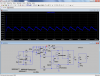
If you can make about a 0.1 ohm resistor and place it in series with the inductor as shown you can then measure the voltage drop across it to find the current with various loads. Then we can try to match it up to spice to see if we can "scope" it.
I don't think it is the high frequency getting to your caps, but the high ripple current (the current put into them by the transformer and taken out by the circuit).
Either way we would know a lot more if we knew the DC current from the supply under different loads.
PS> The resistor needs to be at least 20 watts, so maybe several larger values in parallel.
This site uses cookies to help personalise content, tailor your experience and to keep you logged in if you register.
By continuing to use this site, you are consenting to our use of cookies.