Continue to Site

Welcome to our site!

Electro Tech is an online community (with over 170,000 members) who enjoy talking about and building electronic circuits, projects and gadgets. To participate you need to register. Registration is free. Click here to register now.

  • Welcome to our site! Electro Tech is an online community (with over 170,000 members) who enjoy talking about and building electronic circuits, projects and gadgets. To participate you need to register. Registration is free. Click here to register now.

welder trouble

Status
Not open for further replies.

tonggy

New Member
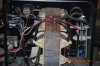
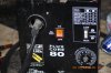
hi, I have a flux core 80watt none gas. I'm new at this field, I'm trying to figure
out why my welder is not giving out any spark at all. I tested the ground wire and the wire is fine, and wire feeder is also working fine. what parts do I need to fix this problem that I'm having with my welder, thanks. ;)
 
Last edited:
What make and model is the welder?

How do you have it set up?

Is there voltage where the cable connects to the welder body?


Torben
 
Here is a schematic for what was described as a MIG welder.
It may be that there is some similarity to a FCAW .... flux core arc welder:
https://www.electro-tech-online.com/attachments/mig-pdf.25650/

..... Maybe take a look at the varister ...... VR1 component .... see if you have something similar ....and it is not shorted out.
..... Actually the problem could be several things ..... transformer winding, diodes ...

Do any of the components look burned or damaged?
 
Last edited:
the name is Campbell Hausfeld and the model WF2000 its set up 115v on 20A,I don't know what else do you mean how its set up. oh there's a little spark like a very small spark not enough to weld and then it goes away
 
not really, but I've seen a fuse in the welder but that fuse only lead to speed nob for wire feed. other then that It looks pretty simple no breaker that I'm aware of but I take a look at it again to see if I'm missing something thanks for responding though.
 
... Just mentioned fuse/breaker because that's what the CH pdf .... attached below.... listed under troubleshooting. It also mentioned a possible cause for no output would be a defective on/off switch.

Since you have observed that the wire motor runs, there is some indication that the on/off switch is functioning.

The circuit diagram on the pdf shows that there are not a lot of parts that can cause the problem that you describe. See p. 9 of the pdf. below.

My next guess would be that something is wrong with the diode bridge.
This is the diamond shaped symbol to the right of the transformer.
The actual part would be a sort of block like object, with four terminals.... two terminals coming from the secondary side of the main transformer .....supplying AC to the bridge. The other two bridge terminals would be the rectified DC .... the DC positive terminal goes to the ground terminal, and the DC negative bridge terminal goes to the actual torch tip .... and welding wire.

If you have a voltmeter, set it to AC and see what AC voltage you can get from the AC terminals of the diode bridge. Guessing that it might be 10 to 20 volts AC .... depending on the weld heat setting. There might be a couple of wavy symbols on the bridge, ~ , to indicate the two AC terminals.

If your AC bridge voltage is within reason, see if you can measure the DC voltage of the bridge.... either at the +/- bridge terminals, or between the torch wire and ground .... might be a little tricky if the weld wire is moving.

Not sure if you have a digital camera .... might be interesting to get a picture of what the work area looks like though.

Watch you fingers .... when you have the welder plugged in.
 

Attachments

  • WF2000.pdf
    1.6 MB · Views: 869
You really need a multimeter (pointer-type VOM (Volt-Ohmeter)) or a DVM (Digital Volt Meter) to even begin to trouble-shoot equipment like this welder. Until March 23 you can get a rudimentary but very handy DVM for the remarkable sale price of $1.99 over-the-counter if you can access a local Harbor Freight retail store. If that is not feasible, you should be able to get a VOM or DVM fairly cheaply at your local Radio Shack store. You really don't need precision or lots of functions for this kind of trouble-shooting.

Then check your machine by following user 88's very good suggestions above. Your machine is about as simple as it's possible to make a welder so you should be able to find out where the problem lies pretty quickly. Your machine has no power contactor so you should see voltage across the welding leads whenever it is plugged in and the power switch is on. The one item that user 88 did not mention is the thermal breaker S3 on the circuit diagram. The "NC" indicates that it is Normally Closed. S3 may be buried in the transformer windings and not be visible, but you will see it's two leads emerging from the windings With the power line unplugged, measure for continuity across those two leads. You could also measure resistance between the two prongs of your power cord. Should see less than an ohm with the power switch at either "ON" position.

If you are not used to making measurements inside a "hot" machine, there are a few guidelines for beginners.

One safety procedure is to only mess around inside the machine when the power is off. Pull the power plug, clip your meter leads to the points of interest, be sure the meter is set on the correct function and range, step back and turn the power on. Make your reading and pull the plug before reaching in and disconnecting the leads. Tedious, but very safe. If your meter did not come with clips for the test leads you can buy a handfull of double-ended clip leads at Radio Shack. Use a little tab of electrical tape or other insulator to be sure you don't inadvertently allow a clip to short against the chassis.

If you do decide to mess around inside the machine while it is powered up, keep one hand in your pocket and use only one hand to apply the clips or reach around inside the machine. Reduces the likelihood that any accidental currents through the body will go through the heart. Wearing rubber-soled shoes or rubber boots helps in this regard, also.

Good luck.

awright
 
Last edited:
Many flux-core welders do not yield good results, especially the inexpensive ones like the C&H and it's Asian produced clones. Shielding gas makes a difference as well as a usable duty cycle. The gun tips clog easily on inexpensive welders, furthering one's problems. Your welder is a 70amp model (not 80watts) and 70 amps is a stretch for welding anything of substantial guage. I'm lucky if I can get my Lincoln to arc at 70 amps! The flux in flux core wire also needs to be of quality - again the cheap stuff just doesn't yield good results. Good weld beads result when using a quality welder, quality rods/wire, a good electrical ground, and proper technique.
 
Well, wait a minute, HiTech. We all start somewhere, usually with beginner's equipment.

I had a similarly amp challenged 115 volt CH of only slightly more power under a different model number for a year or two. I already had been using a 400 amp stick welder for decades after upgrading from a antique Craftsman buzz box that really did a lousy job, but got me started. I bought the baby flux core welder out of curiosity because I ran across it in a salvage store for minimal $. It couldn't do any heavy gauge or structural steel work, but it did get me started on a wire feeder. It worked fine for a number of small jobs on light materials, but it's limitations soon became obvious.

I traded it off and now have a 220 volt 150 amp Lincoln flux core (also bought at auction, this time from my local university salvage outlet in what appeared to be brand new condition) which is still quite limited, but useful for a much larger range of projects.

I started out by crawling. Now I'm walking. Next iteration I'll be running.

awright
 
well Hitech is right on my welder Amps, but the welder did work for me on small projects
and Awright is also right I had to start somewhere this is what I could only afford at the time but its still useful to me. I bought a new one but this time is Lincoln dual mig 35-110amps and 220v. Lets go back you guys said use the volt meter to test the ohms and volt, well I did do the test on the ohms only ,one end of the wire to the other end and including diode and the four terminals. its shows readings like 1.9 and 2.2 I'm assuming that there is no problem but I haven't test the voltage while its plug in or with the switch on . Here is a picture of the welder.
 

Attachments

  • DSC_1580.JPG
    DSC_1580.JPG
    2.4 MB · Views: 3,824
  • DSC_1581.JPG
    DSC_1581.JPG
    2.5 MB · Views: 2,910
In the first photo, the quarter size blue disk to the right, next to the diodes is an MOV or varistor of some sort. It is intended to protect the machine from lightning strikes or similar events.
You might have to unsolder it to test it correctly. It should show a high resistance when you test it with your ohmmeter.

If the MOV is shorted, or defective, you would not be getting 100% of your welding voltage or current.
You might want to make an effort and try to check this one part first.
If it is in fact defective, it would be easy to get a new one.

Typically, MOVs fail if there has been a lightning strike, while the machine was plugged in.

Other things to check:
At the lower left of the same picture is some sort of fuse element ... blue .... on a daughter board next to the switch assembly. I can't tell if it is soldered in place or not. The fuse should measure a low resistance with your ohmeter, or nearly zero ohms.

...Unplug the machine from the wall before you start either of these tests.

.... The diodes, to the right of the picture are the individual bolt on kind, not a block, like I had guessed previously. It looks like there should be two heavy gauge work leads coming from the diodes. These would be your positive and negative DC voltage points.

The data plate in photo two gives a rated value for the maximum open circuit voltage, and also the welding voltage. These numbers would give you a general range to compare your DC voltage measurement to.

What do you think about trying to measure the DC voltage here? This would require the machine to be plugged in and turned on, probably with the trigger switch pressed momentarily, while you read the voltmeter.
 
okay I tested the MOV and it reads 1.2105, is this high? and also I tested the diodes again this time with the voltage running through its reading was very low, more like 4.5v to 7.0v and you said that little fuse that you sough its fine. Do you thing the rust on the diodes could cause this issue? and how much do you think would it cost me to replace the diodes or its not worth it to replace the diodes if this was the problem? I'm a summing the diodes are the heart of the machine.:D
 
When you measured the MOV resistance, did you de-solder at least one end of the part?
You can't get a true resistance measurement across the MOV unless one end is free.
... The other parts of the circuit will interfere with the continuity reading if both ends of the MOV are still soldered in place.
Was your MOV resistance reading 1.2105 ohms? or was it 1.2105 kilo-ohms?
A reading of 1.2105 ohms would mean that the part is defective....

4 to 7 volts DC sounds like it is too low ....
Can you tell which of the wires that are connected to the diode bridge are the AC leads .... coming directly from the transformer secondary. It might be interesting to see the AC voltage reading that these terminals have. If the AC voltage is good, then something is probably wrong with the diode bridge.
 
Last edited:
The rust on the diodes would be a problem if it was interfering with the metal to metal contact of the diode connections. It is more likely that the rust is just external, and is not a factor. However, you might test the integrity of the diode connector by taking a wrench or appropriate tool, and gently twisting the nut ... or even giving the diode body a slight twist ..... The idea is to see that everything is tight, and making good electrical contact.

The diodes themselves are usually fairly sturdy parts ..... not likely to fail. Typically, a problem with the diodes would be in the wires,nuts, washers that are used to connect to them. .... Maybe you could disassemble one or two of the diode connections, and inspect them for rust or oxidation. All the metal contact surfaces should be shiny metal.

I always keep some #400 emery paper to use for cleaning electrical contacts. I also use a spray can of electrical grade contact cleaner... from your favorite parts store. The spray cleaner removes any grease or contamination .... before putting things back together.

Actually, if you were to disconnect the wires from the diodes, your multimeter might have a diode tester built into it. You should expect to see a voltage drop across a diode of about 0.7 volts when forward biased, and a high value .... not exactly sure .... when reverse biased.
 
Last edited:
hey, well I actually cut the MOV from both side. yeah reading were 1.2105 ohms so about the diodes I'll try to do some more test on the ac voltage. about the tightness on the diodes there pretty tight, still I think that if the cost for the diodes is cheap to replace then I should just do that, somewhere on Ebay. or just sell it for junk parts, what do you think? it seam I little to much trouble for me because its starting to give me a headache.
 
If you have removed the MOV disk, and the connections appear to be tight, and the welder still doesn't work, then maybe one or more of the diodes is bad. You should still get a working DC voltage if the MOV is not in the circuit.

It would be a good idea to set your meter to AC voltage, and check the secondary of the main transformer, where it connects to the diode bridge circuit.... If the test points are accessible.

You can check the diodes ... machine unplugged ... but they have to be disconnected from the wires, at least on one end of each diode. Usually, digital multimeters have a diode checker someplace on the dial or faceplate. A silicon diode should read something like 0.7 volts, if it is good .... You should check each diode using both forward and reverse polarity .... meaning the connection of the + and - test leads of the meter. .... If you locate a bad diode, you should be able to buy a new one .....
 
Last edited:
user_88, as best I can decipher the photos, the diodes are the four dark objects on both heat sink plates. One pair is visible immediately above what look to me to be white ceramic insulators with the bolt running through them in the center of the plates. The second pair is visible halfway between the blue MOV and the white ceramic insulators. I think they or their leads are welded to the heat sink plates so the integrity of the connections should be fine but it won't be possible to detach the diodes from the plates non-destructively.

The package style of the diodes I think I am seeing in the photos is shown in the data sheet for the diotech electronics MR821. I tried to grab the illustration of the diode package and paste it here, but failed. You can access the data sheet by clicking on the Diotech version here:

Datasheet Archive - MR821 datasheet - MR821 application note - MR821 pdf

That specific diode only has an average current rating of 35 amps. I assume there is a higher current rated diode in the same package. I pulled this data sheet up because that is the part number of the diode package that I thought I recognized that I had in my junk box.

Actually, tonggy will be able to locate a shorted or open diode in the bridge using the diode test function of a DVM without disconnecting the diodes provided the MOV is still disconnected and provided he can disconnect one end of the transformer secondary from the bridge. That should be easy due to the bolted connection of the transformer leads to the heat sinks. He should see about 1/2 volt in one direction across each diode and "OVERLOAD" or whatever his meter reads on open leads in the other direction.

tonggy, can you see any marking at all on the diode bodies? That would help locate a suitable replacement (but is not vital) in the event that you need a replacement. A suitable replacement should be readily available for a few dollars but you might have to use a stud mount diode.

awright
 
Last edited:
... Just from the photos, I am not seeing any identification on the black diode parts, and it is difficult to see how the diodes are actually installed or attached to the heat sink plates....

.... However, it would be interesting to check the diodes, as per awright's previous instructions, and see if you could find one or two that were defective, or not within a reasonable value.

I think that I would make an effort to measure the AC transformer voltage, at the input to the diode bridge, if this is not too difficult. There might be a poor connection someplace that is the main problem.... And there is a label on the faceplate photo, stating that the machine has a recommended duty cycle. Maybe the transformer is damaged, due to excessive operation when the duty cycle has been exceeded. If the transformer is damaged, it would not be feasible to try and repair the welder.
 
First, tonggy, I think it is always a bad idea to toss an almost usable piece of equipment. Of course, my wife would strongly disagree with me. You are an aha! away from having a perfectly useful (although perhaps limited in capability) light -duty welder. Hang in there. Figuring out where the problem is should not be that difficult. If the transformer is shot you are out of luck but most other components can be replaced or substituted for inexpensively.

Theoretically, the thermal cutoff S4 should protect the transformer against duty cycle exceedances but we know this kind of protection is far from perfect. I agree that measuring the output voltage of the transformer is a necessary step. It should be done open circuit (at least one transformer secondary lead disconnected) and under load. Testing under load requires a large, low-value power resistor. Most guys don't have one but water loads seem to be popular. I've never tried one (because I have a great array of high power low resistance resistors - like the ones that hang under a rail transit car - that I've picked up in my hunting and gathering. Another thread here describes one guy's experience with a water load. Should work for the brief measurement you want to make. See

**broken link removed**

Be careful not to overload your welder.

Let us know what you find with the diodes.

awright
 
Status
Not open for further replies.

Latest threads

Back
Top