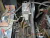
Hello all,I am new here and would like to get some help with my welder that I am trying to repair.I need to replace the 4 resistors in the center of the picture.They are .75 ohm 20 watt and I have been having a great deal of trouble finding that exact combination.Would it be alright to use 1 ohm 20 watt instead or do I need to use some combination?Thanks 50cal
Attachments

Last edited:
 50cal
50cal