Continue to Site

Welcome to our site!

Electro Tech is an online community (with over 170,000 members) who enjoy talking about and building electronic circuits, projects and gadgets. To participate you need to register. Registration is free. Click here to register now.

  • Welcome to our site! Electro Tech is an online community (with over 170,000 members) who enjoy talking about and building electronic circuits, projects and gadgets. To participate you need to register. Registration is free. Click here to register now.

weird keypad??

Status
Not open for further replies.
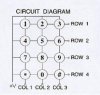
i bought a matrixed keypad from rapid electronics which is 3X4. it only has 7 pins on it, so no +V?? how do i use it? here is a picture of the actual keypad, the one i have is the one on the far left.

**broken link removed**

you can see there are only 7 pins on the picture.

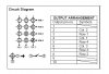
here is the datasheet, which didnt help me at all to be hounest.

**broken link removed**

does anyone have any ideas how to use it?
 
picaxe, using a flowchart, so im trying to think of a way of doing it with a flowchart. also i have used up all of my picaxe chips outputs so i dunno how i can do it?

i might open up the keypad and edit it myself to make something like this
 

Attachments

  • keypad.JPG
    keypad.JPG
    11.5 KB · Views: 204
Last edited:
The title to this thread is misleading, Nemesis.

There is nothing weird about your keypad... it's just like every other matrix keypad available.

If you want complete information about joining a keypad to PICaxe, go to the Feb. 2007 issue of Nuts and Volts magazine www.nutsvolts.com

J. R. Hackett has a detailed article on doing so.
 
well i have never useda keypad before, i thought you would have connected it to high and have 7 inputs and work out what button is being pressed by the row input and the column input. so sorry about the title but i didnt realise it at the time, thats why i put the question mark at the end of the title. anyways i think i have fixed my problem, i have to change some of the inputs on my picaxe chip to outputs which can be done in basic code.

also another thing i want to know about is the number of the pins, for example my kepday has two holes either side of the metal pins, and on the datasheet it says that output pin2 is column two, and output pin 3 is row 1. how do i know which pin is 2 and three? is pin 1 on of these holes? which pin is pin2?
 
Last edited:
Grab a multimeter and throw it on resistance checking, and then you can press keys and see what output does what.

There are many keypad matrixes’ out there, and sometimes you can’t just use someone else’s routine to make your own program.

But they all share a similar approach - make one group inputs, the other outputs, and set one output high, check if any inputs are high (indicating a key press)

Here’s my example;
**broken link removed**
Click here to watch this circuit in action!

And the program (written with Proton+)

Code:
	Device 16F877			' Define what device your using

	XTAL = 4			' Set the Osc speed

	Symbol KeypadTris = TRISC
	Symbol KeypadPort = PORTC
		
	Dim Key as Byte
	Dim Col as Byte
	Dim Row as Byte

	ALL_DIGITAL = True
		
	LCD_DTPIN = PORTB.4	
	LCD_RSPIN = PORTB.2
	LCD_ENPIN = PORTB.3
	LCD_INTERFACE = 4		' Setup the LCD
	LCD_LINES = 2
	LCD_TYPE = 0					
		 
	Delayms	150		 		' Allow LCD to warmup, 
	Cls
		
	Delayms 10
		
	Print At 1, 1, "Press any key..."
		
Main:

	 Gosub Wait_For_Key		  	 ' Loop until a key is pressed
	 
	 If Key = 11 Then		  	 ' If 0 was pressed, change the value of key
	 	Key = 0	 							  ' 
	 EndIf	  								  ' 
	 
	 If Key = 10 Then                        ' Display the data on the LCD, note:
	 	Print At 2, 1, "*"               ' 10 = "*" and 12 = "#"
	 ElseIf Key = 12 Then			
	 	Print At 2, 1, "#"		  '
	 Else	  	 	   		  '
	 	Print At 2, 1, Dec Key		  '
	 EndIf	  	 	   	   	  '

	 Gosub Keypad_Debounce			  ' Wait for the user to depress the key
	 
	 Goto Main				  ' Loop forever

Wait_For_Key:					  ' Loop until any key is pressed
	 
	 Gosub Keypad_Decode
	 
	 If Key = 0 Then Goto Wait_For_Key	  ' If 0 was returned, then loop
	 
	 Return	  		 	  	  ' Input has been captured, return

Keypad_Decode:

	Key = 0			 	  		' Reset the key value
        	  					
	KeypadTris = %00001111			' Make 7-4 outputs and 3-0 inputs
		
        For Col = 4 to 6        		' 4 columns in keypad
                SetBit KeypadPort, Col      	' Set one Col high, 
		Row = KeypadPort & $0F		'  and check if a row is high
		ClearBit KeypadPort, Col	' Set the Col low
		If Row <> 0 Then Goto Gotkey	' If a Row was high, then grab the key
        Next
		
        Return            			' No keys down, then return

Gotkey: 
        Key = ((NCD Row - 1) * 3) + (Col - 3) 	'Calculate what button was pressed
 	   	  		   		' Row = 1 to 4 and Col = 1 to 3
						' So to calculate the key, determine what row equals
						'  by using NCD (Returns a decimal value of the MSB in
						'  the variable, eg, %00001000 would return the value 4
						'  and 00000010 would return 2. Then minus 1 from Row,
						'  so that it is a value between 0 and 3, and as Col
						'  is assigned to the upper part of the port, minus 3
						'  from it so it equals 1 to 3. 
						' Now if Row = 0 and Col = 1 then key pressed = 1 (Row + Col) 
	
        Return         				'Subroutine over

Keypad_Debounce:				' This routine will only exit if
						'  all keys are depressed
		Delayms 10                	' Debounce time
        					' Wait for all keys up
		KeypadTris = %00001111
		KeypadPort = %11110000
		If (KeypadPort << 4) <> $00 Then Goto Keypad_Debounce
		
		Return
 
Nigel Goodwin said:
Check the hardware my tutorial uses - there's no ground or +ve connection to the keypad, it's multiplexed.

yeh i know that now, didnt before i made this thread, my problem with the keypad now is that i dont know which pins are which! where is pin 1? is it the one furthest on the left?


also gramo you say that code is made with Proton+? that looks like basic, i know basic :) might have to check it out.
 
Last edited:
-=GST=- Nemisis (cs/cz) said:
yeh i know that now, didnt before i made this thread, my problem with the keypad now is that i dont know which pins are which! where is pin 1? is it the one furthest on the left?

Like he said, meter on ohms! - or check the pictures in my tutorial! (I used the meter on ohms to find which was which).
 
I urge you to take a look at the datasheet, it's pretty obvious when you think about it.

I've quickly illustrated it for you.
 

Attachments

  • Keypad.GIF
    Keypad.GIF
    13.6 KB · Views: 182
-=GST=- Nemisis (cs/cz) said:
i have to change some of the inputs on my picaxe chip to outputs which can be done in basic code.

I hope you are using an 18 or 18X chip. You should not have to change any pins. You will be using three input (0, 1, 7 or 6 any three) and the four output pins. By the way, that is the March issue of Nuts and Volts.

-=GST=- Nemisis (cs/cz) said:
also another thing i want to know about is the number of the pins, for example my kepday has two holes either side of the metal pins, and on the datasheet it says that output pin2 is column two, and output pin 3 is row 1. how do i know which pin is 2 and three? is pin 1 on of these holes? which pin is pin2?

You only have seven pins, and they are numbered from the left 1 through seven. Refer to your datasheet or the attachment below. Edit: actually, the datasheet calls out 2 - 8, but its the same.
 

Attachments

  • kybrd help.JPG
    kybrd help.JPG
    26.1 KB · Views: 161
Last edited:
-=GST=- Nemisis (cs/cz) said:
thanks! and im using a 28x

Good deal, that should work out okay.

Be sure to look up that article, because you're going to have some serious programming to do. Ron has already done the hard part, and the programs are available (I think) for download.
 
i have almost finished the program. i am not very good at explaining but basically i finished the program a while back and i just needed to know what pins were what :p anyways thanks for the help.

i just have one more question, is there anything stopping me from reversing it and having three outputs and four inputs on my pic?
 
-=GST=- Nemisis (cs/cz) said:
i just have one more question, is there anything stopping me from reversing it and having three outputs and four inputs on my pic?

Nothing stopping you at all, you can also either use pullups (more common) or pulldowns.
 
Status
Not open for further replies.

New Articles From Microcontroller Tips

Back
Top