TheOne
New Member
mechie said:I believe that any decision on whether any waveform is AC or DC must include a clear definition of the voltage reference point used (assuming we ignore steady voltage, varying current scenarios?).
In my attached drawing is a waveform (does it matter about the shape??)
If you use the green line as your point of reference then I think everyone will agree that the waveform is AC (ignoring the pulse wave bit at the end :? - see later)
With the blue line as refernce the same waveform becomes DC? I think NOT - I see it as DC with a superimposed AC waveform - how else would you explain the operation of a simple common-emitter amplifier?
The case of the AC waveform (green ref.) is OK but for the pulse wave as this would tend to result in more energy flowing one way than the other, if a capacitor were used to remove any DC offset then the RED line would be closer to 'neutral' bias.
Maybe this is the key - if there is a neutral net energy flow (flow one way is eventually cancelled by energy flow the other way) then the waveform is AC -- if not then there MUST be some DC present.
https://www.electro-tech-online.com/threads/74190-up-down-decade-counter-help.12304/#post-64556
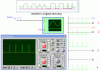
Guys/Gals, you touch a very interesting topic. After reading this post I could not resist in giving the following problem together with a poll as to the correct answer.
Problem as per attachment is as follows:
I show you a scope waveform. The only clues I give you is that it is a pulsed input, frequency 1kHz, 2% duty cycle and an amplitude of 5vp-p
The yellow line is the ground reference setting for the scope.
Question:
From your observation of the scope display and settings, would you say the properties of the input is; (options displayed next to scope)
1/ Pulse with 0v as a baseline reference and +5v as the peak?
2/ Pulse with -2.5v as the baseline and +2.5v as the upper peak?
3/ Pulse with +5v as the baseline and +10v as the peak?
4/ Pulse with -10v as the baseline and -5v as the peak?
5/ Impossible to say?
I will give the answer after a few days or so or the moment we have at least 100 votes.
(Try to answer without digging out your scope to check, and if you know the answer don't post it (just vote) and spoil the fun for others ) :lol:
And don't worry, I can't see who answered what
This was a question to my students once in an exam
Attachments
Last edited by a moderator:
")
