Electro Tech is an online community (with over 170,000 members) who enjoy talking about and building electronic circuits, projects and gadgets. To participate you need to register. Registration is free. Click here to register now.
Welcome to our site! Electro Tech is an online community (with over 170,000 members) who enjoy talking about and building electronic circuits, projects and gadgets. To participate you need to register. Registration is free. Click here to register now.
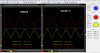
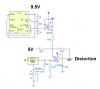
I have a circuit that uses the triangle of a 555 trigger, threshold and is buffered then mixed by a dual opamp. One distorts the triangle and one doesn't, can someone explain why the lm358p distorts the signal?
Can't see the voltages from your pictures, but it looks kind of like crossover distortion that 358's have. Try adding 4.7k from the output of the 358 to ground.
Can't see the voltages from your pictures, but it looks kind of like crossover distortion that 358's have. Try adding 4.7k from the output of the 358 to ground.
Thanks Ron, which voltage are you not seeing?
The only change I made was take the screen shot, change op amps, take the screen shot. I will put a 4.99K in today and take another screen shot.
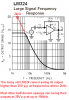
The lousy old LM358 is a low power dual opamp so it is missing the bias current used by all other opamps to reduce crossover distortion. Its low power also causes its performance at frequencies above only 2kHz to be awful. Your 22kHz frequency is much too high for a lousy old LM358 opamp.
Adding a resistor from the output to ground causes its class-B output transistors to operate in class-A. Class-B is low current but causes crossover distortion. Class-A has no crossover distortion if the current is high enough but uses a lot of supply current and the IC will get hot.
THANKS!! I didn't know that the LM358 was such a chunk of junk. I did put a 4.99k from out to ground, but t didn't help. Can you please suggest an op-amp that's generally good for anything.
The LM358 low power causes it to have a poor slew rate. Most opamps can produce full output (plus and minus 14V) at frequencies up to 100kHz or more but the LM358 and LM324 quad have trouble above only 2kHz at levels higher than only plus and minus 10V. The output level of an LM358 or LM324 can go as high as plus and minus 15V but then the slew rate might cause trouble above 800Hz or less (I didn't extend the graph).
This site uses cookies to help personalise content, tailor your experience and to keep you logged in if you register.
By continuing to use this site, you are consenting to our use of cookies.