Continue to Site

Welcome to our site!

Electro Tech is an online community (with over 170,000 members) who enjoy talking about and building electronic circuits, projects and gadgets. To participate you need to register. Registration is free. Click here to register now.

  • Welcome to our site! Electro Tech is an online community (with over 170,000 members) who enjoy talking about and building electronic circuits, projects and gadgets. To participate you need to register. Registration is free. Click here to register now.

Water sensor Help !!!!!

Status
Not open for further replies.

yusuf

Member
Dear friends ?

I don't know if the Sensor Circuit will CONTINUE to work predictably and reliably.

All I can say is that it have done a short test and it worked.


I just dipped two wires (about 1cm apart) - into a tumbler of water.

When I removed them again - they were completely isolated from one another.

So the sensor circuit switched off straight away.

But - after the water level has ceased to cover the actual electrodes - any moisture remaining on the sensor heads - will continue to conduct.

So it's important that the sensor heads should dry-off within a reasonable time.

So friends how to modify this circuit so that the sensor heads should dry-off..

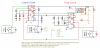
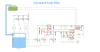
This is my circuit diagram....
 

Attachments

  • Sensor2.png
    Sensor2.png
    12.8 KB · Views: 169
  • Circuit2.png
    Circuit2.png
    18.8 KB · Views: 177
It's the moisture "between" the sensors (wires) that counts, not the water "on" the wires. If they are 1cm apart, then there should not be any water bridging the gap when they are out of the water. That's if I understand you first circuit correctly.

Ken
 
Friend it will be in the deep tank so if any mosture remaining on the top of the sensor will conduct electricity...
So please suggest how to tackle this problem...
 
I think you you need to describe your sensor arrangement in much more detail. Maybe sketch of how the sensor electrodes are mounted. I made a pump controller with a similar AC source, a common electrode (always in the water), and high and low sense electrodes.

Ken
 

Attachments

  • WaterLevelPicaxe03.gif
    WaterLevelPicaxe03.gif
    37 KB · Views: 178
Dear friend This is my circuit of automated tank filler.
And the sensor is modified as in the stimulator I haved send in previous attachment.

So please help ?
 

Attachments

  • automated_tank.png
    automated_tank.png
    181 KB · Views: 170
This circuit is very different than you first one. Were did you get the concept of "powering" your sense transistors (T1-T3) with 6V "AC". The other circuit used AC to "drive" voltage doublers to change the AC to DC to drive the DC powered transistors.

Ken
 
Friend I have made both of them to avoid moisture problem..
Please give me a circuit to avoid mosture problem so that i can put in my tank ...
 
Are you thinking of condensation on the electrodes and across the mounting surface as a possible alternate conduction path? The distance of the water film will determine the resistance of that path between electrodes. The longer the better. So, the only thing I can see is to keep the mounting point at the top of the electrodes as high above the highest water level as possible. Also, coat the upper part of the electrodes with epoxy.

I still think that powering your input transistors with 6VAC is a bad idea.

Ken
 
Friend if you are saying that powering from 6vac is bad idea so please give me a good idea or any good circuit..
Please ...
because i want to complete this project...
thanks in advance...
 
Friend you say powering with 6vav is bad idea so please give me a good idea or circuit because I want to complete this project..
 
You are using the wrong sensor!

The circuit cannot be modified to "dry the moisture off the sensor".

Select a different typoe of sensor such as a float switch and dont rely on the conducting properties of the water.

JimB
 
You are using the wrong sensor!

The circuit cannot be modified to "dry the moisture off the sensor".

Select a different typoe of sensor such as a float switch and dont rely on the conducting properties of the water.

JimB
I've used that type of circuit in 100% humidity environments with no problems. The evaporated moisture is essentially distilled, with a very low conductive ion content. This said, my sensor connections and mount were shielded from dripping condensate. Since, I don't know anything about their container, I can't address whether contaminated condensate dripping from the inside of the container would be an issue.

If this is a real world project, lot more detail about the container would help.

Ken
 
An ex colleague of mine used to design all the electronic circuits for the control on the plant. He designed the following circuit, which was used for sump pump level control.
The probes were made out of 5mm Stainless steel rods placed in a triangular fashion about 1” (25mm) apart. The only problem we had with the probes was that the sumps was often filled with mud, and that started a buildup on the probes. The top of the probe assembly (where the wires are connected to the probes) was always kept way above the high level water mark.

I attach his circuit. It has less components than the one you’re currently using. If I can recall the operating voltage was 24V DC. X-1, X-2 and X-3 are the three probes for the level detection. The common probe (X-1) is as long, or even longer than the Low level (X-3) probe.
 

Attachments

  • Henk(2).png
    Henk(2).png
    23 KB · Views: 171
Last edited:
Status
Not open for further replies.

New Articles From Microcontroller Tips

Back
Top