Continue to Site

Welcome to our site!

Electro Tech is an online community (with over 170,000 members) who enjoy talking about and building electronic circuits, projects and gadgets. To participate you need to register. Registration is free. Click here to register now.

  • Welcome to our site! Electro Tech is an online community (with over 170,000 members) who enjoy talking about and building electronic circuits, projects and gadgets. To participate you need to register. Registration is free. Click here to register now.

Water level detector

Status
Not open for further replies.
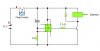
I am looking to build a fairly basic circuit where a water level detector (shown in my diagram attached as a float switch) activates a 555 circuit which has an low output for a time, before going high and activating a solenoid, or in other words, a solenoid controlled by a float switch and activated after a delay. I would like it so that the float switch needs to be active for a given amount of time before the solenoid becomes activated and should the float switch be deactivated at any point the solenoid will remain or revert to a closed state. I have attatched a diagram that is somewhat functional in having a delay before activating the solenoid when the float switch is active, but the capacitor explodes if the float switch is deactivated. Any advice with this topic would be fantastic.
 

Attachments

  • circuit.jpg
    circuit.jpg
    17.2 KB · Views: 187
Just use a standard monostable 555 circuit and put the float switch on the reset pin of the 555.
The 555 reset will need a pullup resistor to +v and the float switch will need to be wired to ground (V-)
 
I would like the delay to be for about 20 minutes, which I understand may not be possible, but it is preferable. The other reason I had looked into designing my circuit like this is that the power from the battery isnt supplied to anything until the float switch is activated, so this system would not drain the battery when the float switch is off (which will be 95% of the time). Would using a standard monostable with the float switch on the reset pin use much power when the float switch is off?
 
See the more information you give the more muddy the water gets.
You failed to mention the power saving requirement in your original post, best you give all the requirements or we are just flogging a dead horse with ideas.

As for your standby power question, i dont know and you can do the test as easy as i can, or perhaps a data sheet might tell you.

Pete.
 
The power saving isn't essential but is certainly preferable, as discussed that float switch will be off for the majority of the time and when switch on I would like there to be a short delay peroid, preferably 20 minutes but again not essential, before activation of a solenoid. Should the float switch be turned of at any time, even when the solenoid is active, the circuit is reset so that the solenoid is deactivated. If this could be done by regulationg power to some sort of a delay circuit via the float switch, it would save battery life considerably!
 
You're not going to be able to get minutes or even one minute of delay out of a 555. Scan through the datasheet and see what test values they use and max them out. IIRC, the max is a few seconds but will be highly variable due to the low charge and discharge rates.
 
In that case what would be a good solution to solve this problem? What about some sort of counting system with a 555 astable and a series of counters? Does anyone know how I might be able to create this delay without using a pic chip and to activate immediately when power is provided to the circuit?
 
Actually you can get minutes, and probably 20 minutes from a 555 timer. There are lots of working circuits that are to 10 minutes or longer. The caviot is to use low leakage timing capacitors and experiment -- Long delays violate the normal equations due to the timer capacitor leakage. If you need longer times, you can always chain a couple timers together.

You're going to need a couple timers anyway, or a dual 556 timer. One sets the initial delay and the other sets the delay after turn-on.
 
Last edited:
I don't have an example, but there are tons of turtorials on 555 timer circuits on the internet. I'd just implement it as two one-shots daisy chained. The first would time out after 20 min or so, then trigger the 2nd, which would activate your circuit. I have a link at home to a good turtorial, I'll try to post it sometime over the weekend.
 
Have you looked at time delay relays? I know that Idec makes some.

These look a little expensive perhaps for what I need, but thank you for the suggestion!

BrownOut:

I have tried your idea of chaining the 555s and it would work but there is a problem, the input on pin 2 needs to go low after going high for pin 3 to go low after the given timeframe. When the float switch turns on it will remain on indefinately (basically until the relay is triggered, which will release water and cause the float to move, thereby deactivating the float switch) and acts as a single pole, single throw switch as apposed to a push switch. Therefore I will need to make pin 2 of the first 555 go low when the float switch is active and then go high again shortly after to prevent pin 3 being high indefinately. I hope that make sense!

I am thinking perhaps it would be better to use an astable and a counting circuit now....
 
I think I have what I want worked out with using a 14 stage binary ripple counter, specifically the CMOS 4020 but there is one last thing I am unsure of now: If I were to cut the power the the IC while it was counting, when power is reapplied would the counting reset?
 
I think I have what I want worked out with using a 14 stage binary ripple counter, specifically the CMOS 4020 but there is one last thing I am unsure of now: If I were to cut the power the the IC while it was counting, when power is reapplied would the counting reset?

hi,
On power down/up, the 4020 could be in any state, its normal to use a power ON reset circuit to ensure that the 4020 is '0'.

To ensure the 'count' continues after a power interruption you would need a non volatile counter.??

When working with CMOS devices the power drain is micro amps, so I would use a small back up battery to keep the CMOS powered during a mains failure.

Note: if you keep clocking the 4020 after the required 20min delay period for a motor turn ON, the 4020 counter if left running would turn OFF the motor 20mins later!. Unless you latch the ON state or stop the 4020 clock.
 
Last edited:
These look a little expensive perhaps for what I need, but thank you for the suggestion!

BrownOut:

I have tried your idea of chaining the 555s and it would work but there is a problem, the input on pin 2 needs to go low after going high for pin 3 to go low after the given timeframe. When the float switch turns on it will remain on indefinately (basically until the relay is triggered, which will release water and cause the float to move, thereby deactivating the float switch) and acts as a single pole, single throw switch as apposed to a push switch. Therefore I will need to make pin 2 of the first 555 go low when the float switch is active and then go high again shortly after to prevent pin 3 being high indefinately. I hope that make sense!

I am thinking perhaps it would be better to use an astable and a counting circuit now....

Just use a capacitor to connect the controlling voltage to pin 2. The voltage will trigger the timer, but go away after capacitor is charged.
 
Just use a capacitor to connect the controlling voltage to pin 2. The voltage will trigger the timer, but go away after capacitor is charged.

This works and so this seems like the route I want to go down, thank you so much for the help! Now however I have another problem! I have connected two 555s as described on this website:

**broken link removed**

But unfortunately when power is cut from the system in my simulator, the capacitor that I have circled in red on my attached diagram explodes.... Am I connecting these together wrong?
 

Attachments

  • circuit.jpg
    circuit.jpg
    32.2 KB · Views: 172
when power is cut from the system in my simulator, the capacitor that I have circled in red on my attached diagram explodes
Can't see any obvious current path of low enough impedance to cause that. However, depending on the internal current paths in a 555 (I'm not up on that) the cap may become reverse biassed. Perhaps that's the effect showing up in the simulation?
 
The simulation is still having problems. A non polarized capacitor seems to work the same as a polarized one but both still blow the 555. I can lower the capcitor to 11 micro F but that still blows the 555. Is it not possible to activate the 2nd 555 with some sort of NPN transistor switch as opposed to how I have done it?
 
Status
Not open for further replies.

Latest threads

New Articles From Microcontroller Tips

Back
Top