Continue to Site

Welcome to our site!

Electro Tech is an online community (with over 170,000 members) who enjoy talking about and building electronic circuits, projects and gadgets. To participate you need to register. Registration is free. Click here to register now.

  • Welcome to our site! Electro Tech is an online community (with over 170,000 members) who enjoy talking about and building electronic circuits, projects and gadgets. To participate you need to register. Registration is free. Click here to register now.

Wall voltage.....

Status
Not open for further replies.
I am in the USA.....
In one of my bedrooms, the plugs read 70-75 volts from Hot to Ground. They measure 122-125 from Hot to Neutral.
That is weird.....isn't it.?
Neutral and Ground are at the same potential are they not.?
Thank You
 
It sounds like you have a broken earth connection. See if the ground to neutral voltage varies when other appliances are plugged in.

You could also see if the ground voltage is the same as the voltage on the water pipes or a ground spike.
 
And do it quickly and safely.

If the main ground link is compromised there is a significant danger of (at the least) appliance damage and (at the worst) fire.

What are the voltages at other outlets?
 
Last edited:
Are you measuring this voltage using a DVM? Due to the high impedance of these devices then simple coupling could give you an erroneous measurement from neutral to earth. It's all about knowing your measuring equipment and how it works as it is about what you are measuring.

This was one of the first lectures we had on an a Diploma in Electronic Engineering course.
 
The standard outlet (120 VAC 60 Hz) wiring in today's US homes should have the neutral and ground connected together at the service entry point. Older homes did not use a third wire ground. Assuming a newer home with correctly grounded outlets you should read line voltage between line hot and neutral and also line hot and ground.

Many older homes in the US still use what was known as Knob and Tube wiring which does not provide for or include a third wire ground. You need to know how your system is wired.

If we assume your home wiring to be newer and correctly installed my guess is a broken or poor ground connection. If you are comfortable checking it yourself I would go to the mains entry and shut off the power to the outlet(s) (circuit breaker or if old fuse) and only once power is removed then remove the outlet and inspect the connections to it. If this symptom shows up on several outlets each branch should tie together at an access point where all the grounds are joined. Somewhere something is likely loose.

Ron
 

Attachments

  • Typ 120 Vac Outlets.jpg
    Typ 120 Vac Outlets.jpg
    25.8 KB · Views: 1,558
  • 120 Volt Outlet Ground.jpg
    120 Volt Outlet Ground.jpg
    41.3 KB · Views: 722
Back in the mid 90's I lived in a older house that had similar strange floating voltages on most of the outlets in the house.
It turned out that somewhere over the years the house had been updated to three prong outlets but all of the wiring behind them was still the original two wire circuitry so non of the three prong outlets ever actually had their ground lines connected to anything.

Having the grounds floating while testing with a high resistance digital meter will result in odd and/or false voltage readings.

The simplest and most honest DIY method I have found to test actual ground circuit continuity is to make a simple three prong plug that runs two small incandescent bulbs. One connected between the hot 120 volt line and the common and the other between the hot line and ground. If both light up then the outlet is properly wired and grounded and if one does not then something is wrong.
 
I like tmctech's suggestion because it draws more current than the neon bulb type test referred to in #7, and they don't necessarily need to be small, it will also test your GFI circuits, if you have any, by tripping them instantly!
I always preferred to test outlets that were giving me problems with a wiggins or Knopp meter because they use a plunger against a spring and pull some power to test. I've also used a 500 Watt flood light as a tester.
 
I like tmctech's suggestion because it draws more current than the neon bulb type test referred to in #7, and they don't necessarily need to be small, it will also test your GFI circuits, if you have any, by tripping them instantly!

But that's all it will test - it's no kind of earth test because the GFI will trip out with a few mA, and to test earth you want to put some decent current through it.

Back a few decades now a standard UK test for fitting washing machines was a 13A plug with a 100W bulb between live and earth, it passed enough current to ensure the earth connection was reasonable.

Not been any use for a long time now though, with the common use of ELCB's/GFI's.

Funnily enough I looked at a TV the other day (Sony 40" LCD) with the complaint it was blowing the ELCB/GFI - didn't here of course, as we don't have one :D (not something you want in a service department).

Anyway, I PAT tested it (class II appliance) and it passed a 1500V 'soft test', which is what they normally do (they fail full tests at 3000V).

As a further 'test' I wired a mains plug to bare wires, and used croc clip leads and my multimeter to measure the actual leakage current to earth - it was 175uA, I also tried a similar era 46" set, with the same result. I later managed to find a 13A line socket, so fitted that to my bare wires, so I can easily do a similar test in the future.

Presumably the actual 'fault' was in the customers ELCB/GFI - which was overly sensitive, I've previously come across a few examples of this.
 
Are you measuring this voltage using a DVM? Due to the high impedance of these devices then simple coupling could give you an erroneous measurement from neutral to earth. It's all about knowing your measuring equipment and how it works as it is about what you are measuring.

This was one of the first lectures we had on an a Diploma in Electronic Engineering course.
He's measuring from hot to neutral and hot to earth, not neutral to earth. For his measurements the DVM should give the correct reading, which should be essentially the same for both conditions if the wiring is correct.
 
He's measuring from hot to neutral and hot to earth, not neutral to earth. For his measurements the DVM should give the correct reading, which should be essentially the same for both conditions if the wiring is correct.

Yeah.......
Anyway, this is a "modern" home, 1988.
Problem occurs in just the master bedroom.
Only reason I checked was because I got a new DMM (Extech EX210) and just wanted to check it. Other rooms in the house measure as they should.
As you guys have suggested, I will have to pull the plugs and find out what is going on.
Probably take a few days, will let you know what I find......or if I need more advice.
Thank You
 
Use your DMM. Put one lead on 'hot' and hold the other in your hand. (touch the lead end with your hand). The meter will read.
I am just trying to show the meter will read 50 to 100 volts when connected to your hand not ground or neutral.
 
Sorry for the delay, I had to have knee surgery all of a sudden. Still recovering.
Anyway......all plugs test fine with the exception of:
1. That one receptacle in my bedroom.
2. All of my GFI.
Number 1 and 2 test the same..."Open Ground"
They also read (in round numbers):
G to N 45VAC
G to H 75VAC
N to H 120VAC

I pulled the one "bad" receptacle in my bedroom and can see no problem with the wiring.

I got 2 extension cords. Plugged one cord into a good plug and one cord into the "bad" plug.
With my DMM, there is NO continuity between the extension cord grounds.
Not sure how "definitive" this test is, but it would appear that little Plug-In Tester is correct.....I have no safety ground on that bad plug.

I cannot tell you why or how this relates to my GFI plugs, which seem to suffer the same disease.

How do I remedy this.? Where do I look for a problem to fix.?
Thank You
 
G to N should be 0 V or real close, certainly not what you see.
G to H should be 120 Volts again not what you see
N to H should be 120 Volts.

You obviously have problems. The ground is not ground among other possibles. The ground and neutral should be tied at the entry point of the dwelling. Interesting how the 75 + 45 = 120. Something is wrong. I just without actually crawling through it am not sure what. Other than ground is not ground.

Ron
 
Yeah, I surely have a problem. It seems I have about 45 Volts on ground of this one receptacle.
Perhaps I should just replace it and see what happens.?
That would certainly be one thing to easily eliminate from the list of possibilities. I will change it in the 'morrow.
Thanks
 
My turn to add some stuff. In the US it is permissible to replace an outlet with a GFCI and no ground if labeled as such.

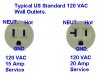
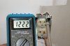
#2. The 1/2 the line voltage happens when there are filters on a circuit, and they are usually symmetrical, so they feed back about 1/2 the line voltage to the ground pin if open. I totally understand where the phantom voltage comes from and why it's usually about 1/2 the mains.

So, in the gist of things, it looks as if you have an open ground. I just troubleshoot one of these problem, but it isn't totally fixed yet.

If it's a metal box, then the device and the box both have to be bonded. You are not allowed to relay on just the screw.

You might trip the GFCI's and see if the bedroom circuit dies.

Although, I haven't had to do this, but what I would do is either use a voltage detector probe or use a circuit breaker locating device, to trace the feed to the outlet with a broken ground.

So, you kinda have to know which outlets are on that circuit and then guess where the wires go. In one of the boxes, the grounds may be just twisted and not wirenutted together. The oxidation breaks the ground even though they "LOOK CONNECTED".

There are some devices and techniques that are helpful. Older boxes do not have a tapped ground screw hole and that makes things difficult. You have to use clips and solid wire. There is a lot of ground stuff here: https://en.wikipedia.org/wiki/E_(mathematical_constant) that's helpful. See this catalog under grounding: **broken link removed**

I can't seem to find a product I use which is a wirenut with a wire coming out of the other end. The solid and stranded pigtails are available in a hardware store.

So, anyway when you find a break in the ground, now you have to guess which outlet feeds the bad one. Yous should be able to trace the wire in the wall with a breaker tracer or AC voltage detector. So, it could feed something downstream or be fed from something upstream. You can disconnect the hot at the bad outlet and you should then be chasing the feeder wire.

Connections can look good, but be bad if they were not done right.

In my case, the ground actually was made from a 50' piece of coax to the coax ground block in the attic. The local ground was missing. So, this outlet was grounded with 16 ohms resistance. The antenna amp has a 3 prong plug and guess what circuit it was plugged into?

So, you may have to (with the power off) measure the resistance of the two touching ground wires with sharp probes.
 
Status
Not open for further replies.

Latest threads

New Articles From Microcontroller Tips

Back
Top