Continue to Site

Welcome to our site!

Electro Tech is an online community (with over 170,000 members) who enjoy talking about and building electronic circuits, projects and gadgets. To participate you need to register. Registration is free. Click here to register now.

  • Welcome to our site! Electro Tech is an online community (with over 170,000 members) who enjoy talking about and building electronic circuits, projects and gadgets. To participate you need to register. Registration is free. Click here to register now.

Voltage-to-Frequency Converter II

Status
Not open for further replies.

km

New Member
I'm having problem in converting square to triangle wave through the AD537 VFC.

Referring to the application notes Figure 28:- https://www.analog.com/UploadedFiles/Application_Notes/511072672AN277.pdf

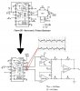
AD537 has the ability to generates triangle wave through the used of AD521 (Precision Instrumentation Amplifier). However, i built an instrumentation amplifier circuit using 3 op-amps (NE5532P)https://www.ampslab.com/PDF/ne5532p.pdf to replace it. The figure is shown in the attach file.

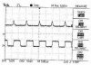
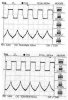
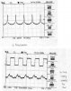
The problem is i can't get the triangle output that i want. Please help me to check what is wrong? Thank You.
 

Attachments

  • VFC.JPG
    VFC.JPG
    76 KB · Views: 234
What output does it make? What is wrong with it?
What frequency?
 
I was getting nothing.

But when i connect either side of the capacitor to Pin 5 of the op-amp (previous figure), it gives something like this
 

Attachments

  • Out.JPG
    Out.JPG
    4.2 KB · Views: 188
So sorry. I just realised one of my OpAmps is not functioning properly.

But after i replaced a new one, this time I got something that looks like triangle? Please look at the attach file. The square wave is the output from VFC.

Why i not getting proper triangle wave?
 

Attachments

  • Triwave.JPG
    Triwave.JPG
    24.8 KB · Views: 196
Last edited:
We have no idea how low is the output level. It is probably too low due to the noise that is seen.
Maybe you are shorting the output with a load resistance much to low.
What are the square-wave and triangle-wave AC and DC levels and what is the load resistance?
 
You mean that is due to some kind of noise?

I have one question to ask. Can we actually get a triangle wave through the use of this instrumentation amplifier?
 
km said:
You mean that is due to some kind of noise?

I have one question to ask. Can we actually get a triangle wave through the use of this instrumentation amplifier?
I asked you to post voltage levels (which you haven't done) because I think the voltage on the cap is outside the common mode range of the IA. It is my fault for not recognizing this before I recommended the 3-op amp version. It requires that the common-mode input voltage be near ground. I'll look into some other topologies. You can use the IA the app note, but it is very expensive (> US $20).
 
The opamps have positive and negative supplies. They should be very happy if the input signal's voltage is near ground (0V).
 
Ron H said:
I asked you to post voltage levels (which you haven't done) because I think the voltage on the cap is outside the common mode range of the IA. It is my fault for not recognizing this before I recommended the 3-op amp version. It requires that the common-mode input voltage be near ground. I'll look into some other topologies. You can use the IA the app note, but it is very expensive (> US $20).

I can't afford to buy the AD521. Is there any other "cheap" methods i can use?
 
I looked at your existing IA again. It should work. Check your wiring carefully. The unused op amp section must not be left with floating inputs. Connect the output to the inverting input, and connect the noninverting input to GND.
Your input op amps (connected to the timing cap) should have FET inputs for best performance, because the capacitor current must not be altered. The NE5532 can have bias current as high as 0.8 uA.
 
I replaced the NE5532 with TL082... But still i can't get the triangle output.
The attached file shows the output i got. +12 n -12V is the supply voltage for the op Amps.
 

Attachments

  • VFC_1.JPG
    VFC_1.JPG
    21.9 KB · Views: 191
105kHz is too high for an NE5532 or a TL082 opamp to reproduce a triangle wave. Their power bandwidth is up to only 100kHz so the harmonics of 105kHz are not passed. Try a max frequency of 5kHz or 10kHz.
 
audioguru said:
105kHz is too high for an NE5532 or a TL082 opamp to reproduce a triangle wave. Their power bandwidth is up to only 100kHz so the harmonics of 105kHz are not passed. Try a max frequency of 5kHz or 10kHz.
The TL082 100kHz power bandwidth (with ±15V supplies) is due to the slew rate limitation of 8V/usec (a 13V peak, 100kHz sine wave has a slew rate of 8.17V/usec). The test circuit also has a gain of -10, and a 100pF cap load. A triangle of a given amplitude has a lower slew rate than a sine wave of the same amplitude, and I also doubt that his IA amplifiers need to swing to their output limits, so this makes the slew rate even lower. A 3MHz GBW op amp has adequate bandwidth to pass a 100kHz triangle with a feedback ratio of 0.5 (inverting gain of 1 or non-inverting gain of 2). In this case, the closed loop BW will be 1.5MHz, which means it will pass all harmonics through the 15th with less than 3dB attenuation. A simulation bears this out. I think a hardware test would have similar results.
 
Hi Ron,
Of course! A triangle wave is the output of an opamp that has slew-rate limiting. With the amplitude not at max then the opamps will work fine at 105kHz.
 
Hi, i'm not sure whether i'm getting the results, please have a look at it at it.
Why the amplitude is so small compared to the VFC square wave output?
 

Attachments

  • triwave2.JPG
    triwave2.JPG
    46.9 KB · Views: 165
km said:
Hi, i'm not sure whether i'm getting the results, please have a look at it at it.
Why the amplitude is so small compared to the VFC square wave output?
What did you change in order to get these waveforms? They look better, but still not right. Something is wrong with your instrumentation amplifier.
 
i used the same resistor values shown in Figure 21:-
**broken link removed**

The others connection remain the same. (Op-Amp supply is 9V n -9V)

The first figure is about when i minimize the 1k potentiometer. The second figure is when i reduce the op-amp supply voltage.

What should i suppose to get for a correct triangle waveform? The triangle waveform looks very small (50mV/division) compare to the Square (5V/division).
 

Attachments

  • analysis.jpg
    analysis.jpg
    53.8 KB · Views: 156
Status
Not open for further replies.

Latest threads

New Articles From Microcontroller Tips

Back
Top