Continue to Site

Welcome to our site!

Electro Tech is an online community (with over 170,000 members) who enjoy talking about and building electronic circuits, projects and gadgets. To participate you need to register. Registration is free. Click here to register now.

  • Welcome to our site! Electro Tech is an online community (with over 170,000 members) who enjoy talking about and building electronic circuits, projects and gadgets. To participate you need to register. Registration is free. Click here to register now.

Voltage sensor/LED indicator with transistor as switch

Status
Not open for further replies.

bill_w

New Member
I'm designing a fixture that takes a DC input from a power supply and essentially just passes it through to another device. Essentially it consists of a breaker and a switch.

I want to build in an indicator circuit to light an LED when the input voltage is within 10% of the required 28VDC.

I wanted to use a FET, but we do not have any in stock that will work with my voltage levels, so my next best thing is a BJT.

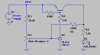
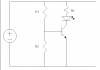
My thought was to use a voltage divider set up so that Vbe would be 0.6V when my Vin is roughly 25V. Then I have the LED on the collector with a current limiting resistor. See my attached diagram please.

I've done my homework, but I'm not sure if I fully understand the operation of the BJT. I haven't done this since school...

For R1 I've calculated 330ohms, R2 a 4.7 and 3.3 to get 8ohms. R3 is 1.2kohms to limit my LED current to roughly 20mA. My voltage divider is set up to provide .6V across R2 and Vbe @ 25.35VDC in. Have I done this right? Do I control base current with the collector current, or is it the other way around? I want my Ib to be ~2mA.

If it helps, it is a 2V LED. Specs on the transistor are Vcesat=.3V, Vbesat=.6-1.2V.

Not looking for an answer, just helpful hints. Maybe a little push in the right direction.
 

Attachments

  • LED_Circuit..doc
    54 KB · Views: 415
Last edited:
Please don't use Word for schematics, use PNG or GIF.

That circuit won't be very accurate because the base voltage will vary quite widely.

The values of R1 and R2 are much too low, I'd recommend 6.8k and 180R.

The LED will also come on pretty gradually as the voltage rises, is this all right or do you want a sudden switch on?

EDIT:
R3 should also be higher, I'd recommend 2.2k
 

Attachments

  • LED voltage monit.PNG
    LED voltage monit.PNG
    1.3 KB · Views: 709
Last edited:
Can you elaborate slightly on the higher resistor values?

And I would prefer for the LED to be noticable at 25VDC in... Thats why I tried to calculate for 20mA at 25V, hence the 1.2k resistor.

The sudden switch on was the reason for initially choosing a FET, but I do not have authorization to buy the proper FETs and we only have BJTs in stock downstairs.
 
Last edited:
20mA is too high and what about the current when it's 28V?

The resistor values are calculated using the potential divider formula.
Voltage divider - Wikipedia, the free encyclopedia

The base voltage will be 0.65V when the input voltage is about 25V.

Actually I didn't bother, I cheated, I used a program called ResistorCAD to generate the correct values. :D Unfortunately the program seems to have disappeared from the Internet so I can't link it. :(

A MOSFET won't give you sudden switching, you need two transistors to do that.
 
My LED is rated at 50mA max continuous forward current.

With 2.2k for R3, I get 10mA at 25V, 12mA at 28V. Is that even visible?
 
All right then it seems liek 20mA would be fine.

10mA would definitely be visible.

The problem is many people run LEDs at the absolute maximum forward current continuously, then wonder why they burn out.

For 20mA, keep 1.2k for the LED.
 
Ok good deal. So the circuit will work, albeit maybe not so accurately? I will do some breadboard tests once the LEDs come in.

Thanks for your help.
 
Here is a sim of some ideas. The plots are LED current vs power supply voltage. The first circuit sucks. Moving the LED to the emitter, and using it as sort of a poor man's zener makes the circuit work better. I would do it the third way because I have a bunch of LM431 sitting around.
 

Attachments

  • E14.png
    E14.png
    45.6 KB · Views: 587
Last edited:
Mike, what application did you use to do that? I can't seem to find any circuit analysis/simulation tools in our software library... Seems strange, given our line of work...
 
A MOSFET won't give you sudden switching, you need two transistors to do that.

I was under the impression that a turned on MOSFET was pretty much like a short... Can you point me in the direction of more info on this two transistor setup? Sudden switching would be best.
 
That's true but only, once the MOSFET is fully on.

Just like with a BJT, it's possible for a MOSFET to not be fully on which will cause the LED to light dimly.

To snap on, you need some hysteresis. Here's an improved version of Mike's circuit.

It's also possible to do it with BJTs and a normal zener but it won't be as good.
 

Attachments

  • LED voltage monit.PNG
    LED voltage monit.PNG
    3.2 KB · Views: 406
Last edited:
Would a circuit like the attached be practical for this application? Using 1/2 of an LM 339 as a window comparator with a divided input the user could set a window of 28 Volts + or - 10%. The LED would only be lit when the applied voltage was between 25.2 volts and 30.8 volts. A known value of 28 VDC is applied and the wiper of RR6 is adjusted for 7.0 volts. Then the wiper of R3 is adjusted for 6.3 volts and the wiper of R1 adjusted for 7.7 volts.

The output could drive the LED or anything else like a small relay to prevent the 28 volts from being passed on unless it was in limits. The circuit is a rough and filtering on the 7812 wasn't included. I was just thinking that even if not a window comparator maybe a simple comparator could be used. It would offer a pretty clear On or Off (snap) for the LED.

It's late and 4 AM comes early so I am out of here. :)

Ron
 

Attachments

  • LM 339 Comparator&#46.png
    LM 339 Comparator&#46.png
    7.6 KB · Views: 321
Mike, what application did you use to do that? I can't seem to find any circuit analysis/simulation tools in our software library... Seems strange, given our line of work...

LTSpice. Free download at linear.com Check out the LTSpice User's Group on Yahoo.com. You must register to view the content, but there are lots of knowlegable folks, sample circuits, and models there. Any question you come up with has probably been asked before, so be sure to use the Search feature before just blasting out a question.
 
Would a circuit like the attached be practical for this application? Using 1/2 of an LM 339 as a window comparator with a divided input the user could set a window of 28 Volts + or - 10%. The LED would only be lit when the applied voltage was between 25.2 volts and 30.8 volts. A known value of 28 VDC is applied and the wiper of RR6 is adjusted for 7.0 volts. Then the wiper of R3 is adjusted for 6.3 volts and the wiper of R1 adjusted for 7.7 volts.

The output could drive the LED or anything else like a small relay to prevent the 28 volts from being passed on unless it was in limits. The circuit is a rough and filtering on the 7812 wasn't included. I was just thinking that even if not a window comparator maybe a simple comparator could be used. It would offer a pretty clear On or Off (snap) for the LED.

It's late and 4 AM comes early so I am out of here. :)

Ron

That definitely looks more robust, but I am limited by time and budget. I was just instructed to build a fixture with an LED to indicate power... Then I opened my mouth and asked if he wanted the LED to indicate the power within a certain tolerance, and he said yes. So I am trying to make it work with limited resources, basically the parts we have down in the factory. No PCB allowed, and comparators and op-amps didn't get put on the BOM.

I'm not sure where I would get a reliable +12V, the input to this fixture is going to be an adjustable DC power supply. Really, the light is just there in case the power supply is really messed up, or the production tech testing the unit is really stupid and can't follow the test procedure. If they can't set 28V properly, they won't be able to set 12V either.
 
The trouble is, to get the snap on you're looking for you need hysteresis which requires positive feedback which needs two gain stages.

Here's an example with a couple of transistors.

When the voltage on R2 exceeds the zener voltage plus the turn on voltage for Tr2, Tr2 turns on, which connects Tr1's base to 0V via R4. R3 provides positive feedback by further increasing the voltage on R2 once Tr1 turns on a bit. Once it's on, the voltage needs to fall below 24V or so before it turns off.
 

Attachments

  • LED voltage monit.PNG
    LED voltage monit.PNG
    1.3 KB · Views: 378
That definitely looks more robust, but I am limited by time and budget. I was just instructed to build a fixture with an LED to indicate power... Then I opened my mouth and asked if he wanted the LED to indicate the power within a certain tolerance, and he said yes. So I am trying to make it work with limited resources, basically the parts we have down in the factory. No PCB allowed, and comparators and op-amps didn't get put on the BOM.

I'm not sure where I would get a reliable +12V, the input to this fixture is going to be an adjustable DC power supply. Really, the light is just there in case the power supply is really messed up, or the production tech testing the unit is really stupid and can't follow the test procedure. If they can't set 28V properly, they won't be able to set 12V either.

Understand. Oh the 12 volts comes from a 7812 regulator in the circuit. Anytime the input voltage is above about 14 volts the circuit is active running off the fixed 12 volts. That way the circuit isn't effected by variations in the input voltage. No problem, I just thought I would toss a comparator circuit out as a suggestion. Never offer added features. :) Been there and done that.

Hero has a good angle and that should work out for you.

Ron
 
Status
Not open for further replies.

Latest threads

Back
Top