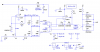
I need to maintain pressure on a hydraulic system within a narrow +-3% band for some tests but the commercial precision pressure switches are way out of my budget . I have a 4-20ma pressure transducer that I can drive at 24V with a maximum 700 ohm shunt resistor (Say 680 ohms). I need a switch that will turn the pump on when the voltage drops below 4.35V and off when it reaches 4.45V.
I have been experimenting with an LM1458 dual op amp and some 10K trimmer pots I had on hand and can get a pair of LED's to light as the input voltage goes high or low outside the .1V range but I am having a brain freeze on how to latch a relay on when the low op-amp turns on and off when the high op-amp turns on. I can change the logic by reversing the op-amp inputs but any way I do it the pump will turn off as soon as the pressure gets within the range. There will be no deadband so the pump will cycle rapidly. Ideally the pump should cycle for maybe 10 seconds every 4 or 5 hours.
Any suggestions?