Continue to Site

Welcome to our site!

Electro Tech is an online community (with over 170,000 members) who enjoy talking about and building electronic circuits, projects and gadgets. To participate you need to register. Registration is free. Click here to register now.

  • Welcome to our site! Electro Tech is an online community (with over 170,000 members) who enjoy talking about and building electronic circuits, projects and gadgets. To participate you need to register. Registration is free. Click here to register now.

Voltage regulator

Status
Not open for further replies.
So...just use a voltage regulator like 9-9.5V with lm317 an conect in series 3 LED's. The circuit wil protect them from any spykes and the curent trought the led's it's fixed.
Or....use a current regulator if u like
Or use a ultra low dropout reg
All 3 will protect the leds from spykes and so on
The current reg might fry the leds thought if higher voltages are coming in.
 
Hero999 said:
You can use an LM317 constant current source to power LEDs from a wide voltage range.

But you can make a 12V regulator from a 13.8V source, you need a very low dropput regulator.

ultra-low-dropout-gif.9392

Use a P-Ch MOSFET instead and one would not need the many components of the 555 voltage doubler. Of course one has to swap also the two inputs of the opamp.
 
Last edited:
Of course, in fact this was adapted from a circuit using a p-channel MOSFET but p-channel MOSFETs have a higher on resistance, therefore it will have a higher drop-out voltage.
 
Hero999 said:
Of course, in fact this was adapted from a circuit using a p-channel MOSFET but p-channel MOSFETs have a higher on resistance, therefore it will have a higher drop-out voltage.

Agree. N-Ch MOSFET is also more readily available and cheaper.
 
Tarsil said:
I was thinking about geting a 9V or so voltage.
About the circuit above....can't I just use a zener diode and a logic mosfet?
Or maybe I'm wrong about the role of the 555 circuit.:confused:
I was answering the origional question.
 
The 555 is a voltage doubler oscillator that powers the opamp with a supply voltage that is nearly double the supply. Because the gate voltage of an N-channel Mosfet needs to be up to 10V higher than its source voltage.

If you use a zener diode connected to the gate of an N-channel Mosfet, then its source (output) would be up to 10V lower.
 
I had seen this circuit posted before so thought i'd try it. It works very nicely indeed. Not certain of it's working though, the MOSFET can only be switched on or off? So how does it regulate? Is it as soon as the voltage goes over, it switches off, then the output drops back and it turns back on? So it effectively switches on and off quickly to keep the output within the limit? If that is true, presumably is doesn't waste power as heat so much either?
 
Hi Dr. EM,
The 555 is a DC to DC voltage doubler as a high voltage supply for the opamp. See my previous post.

The N-channel Mosfet is a linear source-follower. It gets VERY hot.
A circuit can be designed for a hot P-channel Mosfet and won't need an oscillator to make a high voltage supply for the opamp, but it is tricky to stop it from oscillating because then the Mosfet would have voltage gain which adds to the opamp's voltage gain.
 
Yeah, but how i'm seeing the design is that the input to the MOSFET gate is either high (about 2x the supply voltage), or low (ground). And as such the MOSFET is either on or off? How is it that it functions linearly? I must be missing something.
 
Dr.EM said:
Yeah, but how i'm seeing the design is that the input to the MOSFET gate is either high (about 2x the supply voltage), or low (ground). And as such the MOSFET is either on or off? How is it that it functions linearly? I must be missing something.

It's called 'negative feedback', the FET isn't switched ON or OFF, it's being fed from an opamp, NOT a logic gate. Even though it's wired as a comparator the output will be an analogue voltage within it's required parameters - so if the output increases slightly, the output of the opamp will change to compensate for it. The capacitor across the output helps it all to stabilise, otherwise it would tend to switch.
 
audioguru said:
The 555 is a voltage doubler oscillator that powers the opamp with a supply voltage that is nearly double the supply. Because the gate voltage of an N-channel Mosfet needs to be up to 10V higher than its source voltage.

If you use a zener diode connected to the gate of an N-channel Mosfet, then its source (output) would be up to 10V lower.
I haven't used enought words.:D The zener diode was for asuring a stabilized voltage for the comparator/opamp and i was thinking about using a logic MOS-FET. That type is fuly open at only 4-6V aplied to the gate. In this case the voltage doubler is useles.
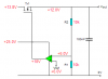
 
Nigel Goodwin said:
It's called 'negative feedback', the FET isn't switched ON or OFF, it's being fed from an opamp, NOT a logic gate. Even though it's wired as a comparator the output will be an analogue voltage within it's required parameters - so if the output increases slightly, the output of the opamp will change to compensate for it. The capacitor across the output helps it all to stabilise, otherwise it would tend to switch.

Thats what confuses me, it's wired as a comparator, so I thought it could only be high or low? How is it able to produce varying voltage, does it's supply from the 555 circuit change accordingly?
 
Dr.EM said:
Thats what confuses me, it's wired as a comparator, so I thought it could only be high or low? How is it able to produce varying voltage, does it's supply from the 555 circuit change accordingly?

Like I said, it's an opamp, NOT a logic chip - as it goes from -ve to +ve, it obviously has to pass through all the linear voltages possible in that range. So by VERY accurate adjustment of the input voltage you can get a linear voltage swing from the output, for a VERY small input voltage change.

Due to the massive gain of the opamp this input voltage change is too small to do manually, but the negative feedback does it automatically, continuously altering it to keep in the linear region. Pretty well any regulated PSU with feedback works in this way!.
 
The Mosfet is at the ouput of the opamp and is included in the opamp's negative feedback loop. So if the resistors have an equal value then the opamp-Mosfet amplifier has a voltage gain of 2. If the Ref voltage is 6.0V then the output will try to stay at 12V even if the output is nearly shorted.

I have the Mosfet shown with its gate-source bias at only 6V but it could be as low as 3V or as high as 10V.
 

Attachments

  • Mosfet regulator.PNG
    Mosfet regulator.PNG
    7 KB · Views: 326
audioguru said:
A circuit can be designed for a hot P-channel Mosfet and won't need an oscillator to make a high voltage supply for the opamp, but it is tricky to stop it from oscillating because then the Mosfet would have voltage gain which adds to the opamp's voltage gain.
No problem, add a 100k resistor in series with the MOSFET's gate, this act with the cate capacitance to form a low pass filter which will preven oscillation. I prefer the N-channel follower anyway because it has a lower dropout voltage.
 
I find with LED's which are rated for 20 mA running current that they perform very well at 10 to 15 mA with hardly any noticeable drop in light output.

To aim for say 12 mA as a safe value will allow for some voltage swing in your 12 - 13.8 volts without overstressing any LED whatsoever if you calculate the series resistor to allowe for that current flow.

Or take the constant current source option which will be a little more work but vey effective. and no variation in LED brightness.
 
Status
Not open for further replies.

Latest threads

New Articles From Microcontroller Tips

Back
Top