Continue to Site

Welcome to our site!

Electro Tech is an online community (with over 170,000 members) who enjoy talking about and building electronic circuits, projects and gadgets. To participate you need to register. Registration is free. Click here to register now.

  • Welcome to our site! Electro Tech is an online community (with over 170,000 members) who enjoy talking about and building electronic circuits, projects and gadgets. To participate you need to register. Registration is free. Click here to register now.

Voltage regulator current limit active indicator

Status
Not open for further replies.

diy didi

Member
Hi Guys.
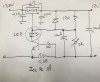
I build the attached circuit. Instead os the LM317 I used a LDO LM1086 regulator. It has the same pinouts, and works a treat.
My question relates to the LED in my circuit. I added it from memory from an old school power supply I built which added an LED in the collector of the transistor to indicate a "current limit" state.
Problem is, that the LED changes the limiting current slightly, and the rate of current limit drastically. The LED also lights up very early, long before the calculated limit value.
Is there a better arrangement that I can use here. I know that the datasheets don't show the LED, but would be awesome to have some form of indication.
 

Attachments

  • Reg.jpg
    Reg.jpg
    544.5 KB · Views: 479
Add a resistor in parallel with the LED to reduce it's sensitivity.
You would need to experimentally determine its value but it should be in the neighborhood of a a couple hundred ohms or so.
 
https://www.ti.com/lit/ds/symlink/lm317.pdf

lm317 needs vin to be at least 3v above vout....I noticed your vin is 13.8v and your vout is 12v, so you might not have enough headroom...it may depend on the load level....ill take a further look in the datasheet, but 3v is typical for the amount of hedroom needed. I am not sure how your short cct thing works, because as soon as the fault current flows, then the lm317 turns off, so your protection cct deactivates, then the lm317 starts up again, etc etc....
 
I will have a look at your simple setup, but a more exact one is as follows, which gives you 12v, and limits to 1A exactly whereas your bjt based limiter is inaccurate.
The LED lights up whenever the output current goes above 800mA.
The output voltage will reduce as the load gets heavier, such as to limit the output current to 1A MAX.
The schem is here, but also the ltspice simulation, which you can run in ltspice, just change the .txt file to .asc, and hit the running man icon in the simulator..which is free download
 

Attachments

  • Schematic _12V linear regulator _1.pdf
    18.5 KB · Views: 187
  • 12V linear regulator _current limited _1.asc
    8.1 KB · Views: 174
Last edited:
The output voltage will reduce as the load gets heavier, such as to limit the output current to 1A MAX.
:confused: I'm seeing about 1.8A if I change the load in the sim to 5Ω. I suspect the LTC6102 isn't happy with the lower supply voltage.
 
good point yes, if it drops that low then it wont handle it, and some extra cct would be needed, as the ltc6102 needs 3v minimum.
There is an equivalent LT1086 so if OP is still stuck I will mod up the original cct, I don't think op can have the led where it is....I think I would drive the led in some way deriving from the input voltage....but yes, the npn pulling the adj pin to ground is going to shut off the regulator and solve the overcurrent.
By the way I wouldn't be surprised if lm1086 needs 3v headroom, at least for heavier loading.
 
We saw how the above circuit doesn't work with hard shorts, but can handle reasonable overloads, but this one here is handling that, and runs in the free ltspice.
There are two alternatives so you can pick.
They use the LT1086 but this is just the same an your LM1086
 

Attachments

  • LT1086 _schematic.pdf
    19.7 KB · Views: 205
  • LT1086.asc
    6.2 KB · Views: 145
Flyback, I built your second circuit with the two transistors, and the led does go on when shorting the output.
 
I take it you mean the simplest circuit. (the bottom one of post #8) I suppose the ADJ pin goes to a low voltage but not zero......in the ideal case the LM1086 would turn off and there'd be nothing to keep q2 on, but I guess that with the general hysteresis of the circuit, the q2 ends up in linear mode and just drives the led.
 
I was going to offer an alternative which has a latching circuit which gets “armed” shortly after power up, and then totally shuts off the regulator after an output short circuit or overload (and switches a led on)……and then waits for the user to push a button so as to reset the latch and to allow the regulator to start again. (ie in the hope that the short has been removed).
This is called Latching short circuit protection.
The other type is called “shutdown-and-retry”, which does what it says it does.
The way it is being done in your circuit is just to kind of limit the short circuit current and light the led. I suppose its using the short circuit limiter inside the lm1086 itself
 
I've had trouble with the same thing, the circuit is very simple so you wont get a decisive switch on.
The led will introduce a voltage drop so if your o/p voltage is low it might not even light up, red leds have a low vdrop at around 1.6v.
 
True I think op ended up using the bottom circuit of post#8, using the vin to light the led......the cct of top post, I agree doubtful to work. Can always try it with the lt1086 in ltspice simulator (lt1086=lm1086)
 
Status
Not open for further replies.

Latest threads

Back
Top