johankj
New Member
I'm having a problem with my voltage divisor network, which is basically set up as in the drawing (simplified).
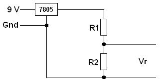
I want to read the voltage across R2 (Vr), but allas...
My problem is that there is a resistance across the regulated output of the 7805 and ground of roughly 4k. My R1 value is 100k, and the R2 is a 100k variable resistor.
When assembled, R1 and R2 reads ~50k, I suspect because of the lower resistance across the 7805.
Is there a way to fix this? Or even better, can I completely ignore this?
")
