Continue to Site

Welcome to our site!

Electro Tech is an online community (with over 170,000 members) who enjoy talking about and building electronic circuits, projects and gadgets. To participate you need to register. Registration is free. Click here to register now.

  • Welcome to our site! Electro Tech is an online community (with over 170,000 members) who enjoy talking about and building electronic circuits, projects and gadgets. To participate you need to register. Registration is free. Click here to register now.

Voltage regulation

Status
Not open for further replies.

Riofun

New Member
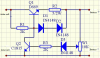
Hi all, i am building a voltage regulation circuit providing a stable voltage of 1.45v to charge a 1.2v battery and I`d like to hear from you guys that are there any modifications or improvements can be made to this design ?

Calculations have already been done:
Vout is 1.45v
voltage cross R1 is 1.95v
R1 = 177 ohm
voltage cross ZD1 is 2.05v
 

Attachments

  • vr.JPG
    vr.JPG
    16.7 KB · Views: 193
You need to think again, you don't charge with voltage, you charge with current - the voltage just needs to be high enough to provide the required current. Usual way would a simple resistor, or a constant current source.
 
A zener diode with a voltage as low as only 2.05V is a very poor regulator. Its voltage changes with temperature and current and also the base-emitter voltage of the transistor changes with temperature and current.
There is nothing to limit the charging current in your extremely simple circuit.
 
A zener diode with a voltage as low as only 2.05V is a very poor regulator. Its voltage changes with temperature and current and also the base-emitter voltage of the transistor changes with temperature and current.
There is nothing to limit the charging current in your extremely simple circuit.

Thx for your reply. I know this circuit is simple. Can you give me any advice on how to improve the circuit then? many thx
 
Use a battery charger IC to charge a battery, not a bunch of parts that do it wrong.
Learn about battery chargers.
 
Use a battery charger IC to charge a battery, not a bunch of parts that do it wrong.
Learn about battery chargers.

Can you give me any advice on how to choose battery charger IC if the power source is unstable, like solar power.
DS2714-Maxim is fine to charge the 1-4 AA battery but it needs regulated current source.
 
If the power source power is high enough then a battery charger IC works perfectly.
If the solar cells are in a cloudy day or at night then "duh" the battery will not charge properly.
 
If the power source power is high enough then a battery charger IC works perfectly.
If the solar cells are in a cloudy day or at night then "duh" the battery will not charge properly.
It seems to be a problem but I only use this DIY circuit during the sunny days. I am not sure whether DS2714-Maxim is a proper IC for my circuit ? Any suggestions ? Thx
 
Most cheep patio solar lights just use a diode and let what ever happens,happen. But the batterys do not last long. Andy
 
Hi all, can you have a look at my circuit below. Fitst of all, Q1 will be active to charge the battery. Once the voltage across the battery reaches 1.44V, the Q2 will be active and shut down the Q1 to stop the battery charge. I am not sure whether the design is proper or not ?

Any advice is welcome. Many thx.
 

Attachments

  • charge.png
    charge.png
    199.5 KB · Views: 192
You may be working to hard.
What is the output of the solar panel. What kind of battery?
 
That design is well known and will work if the resistor values are correct and the pass transistor can survive the heat, but I can't remember what D1 and D2 are for. (I think they are not necessary.)
 
That design is well known and will work if the resistor values are correct and the pass transistor can survive the heat, but I can't remember what D1 and D2 are for. (I think they are not necessary.)

I am not sure the values are correct or not. My solar panel output is 4V@200mA.
 
Q2 and D3 are thermometers. They conduct at a lower voltage as they get warm.
 
Q2 and D3 are thermometers. They conduct at a lower voltage as they get warm.

Q2 conducts once the voltage across the battery reaches 1.44V, can you explain more of your opinion.

I don`t know much about the Q2 part. Can someone explain its principle ?

many thx.
 
Last edited:
IF it is a AA NiMh battery C/10 is 250ma or so. You can just add the diode mentioned in a prior post and let'er rip. The solar panel is you current limiter.
 
Q2 conducts once the voltage across the battery reaches 1.44V, can you explain more of your opinion.

I don`t know much about the Q2 part. Can someone explain its principle?
Q2 begins to conduct when the voltage at the slider of the trimpot reaches about +1.3V (0.65V for D3 plus 0.65V for the base-emitter voltage of Q2. But the diode and base-emitter junction conduct at lower voltages when they get warm.

When Q2 conducts then it reduces the voltage and current at the base of Q1 so the output voltage of Q1 is sort-of regulated.

Instead of using the Mickey-Mouse voltage regulator circuit you could use an LM317 voltage regulator IC set to exactly 1.44V. A series resistor could limit the max current and the trickle-charge current will be very low when the battery cell's voltage reaches 1.44V.

LM317 seems to be OK but it requires at least 3V input and the solar power is unstable.
 
Status
Not open for further replies.

Latest threads

Back
Top