Continue to Site

Welcome to our site!

Electro Tech is an online community (with over 170,000 members) who enjoy talking about and building electronic circuits, projects and gadgets. To participate you need to register. Registration is free. Click here to register now.

  • Welcome to our site! Electro Tech is an online community (with over 170,000 members) who enjoy talking about and building electronic circuits, projects and gadgets. To participate you need to register. Registration is free. Click here to register now.

Voltage regulated high current pulse generator. (L meter)

Status
Not open for further replies.

Blueteeth

Well-Known Member
Hi,

After tinkering with lots of transformers for switch mdoe power supplies, I've concluded by humble LCR meter just isn't up to the task of measuring inductance on multiwinding coils (transformers). It seems to give wacky results when theres more than a single winding. So I'm knocking up my own meter to measure L (reasonable accuracy), as well as saturation current. This is all without an oscilloscope as I can't be botherd to set it up every time I want to check something.

So, the question. Given I=(V/L)*t, I'm tihnking pulse the inductor at a low voltage, but with available high current (<10A) until it reaches a set current.

As I don't really want to use a 10A supply with this (possibly portable, but preferably a fairly moderate 12V @ 500mA wall wart power supply) I'll obviously need a large capacitor to provide the pulse. Because the above formula relies on a constant voltage across the inductor, simply using a cap, the voltage would obviously drop as it discharges. Any idea's on a method to 'charge up' a cap bank, say 3000uF-10000uF with lower current at 12V, but using this as a power supply for say 2V @ high current for < 100uS ?

I know I could always jst use a HUGE cap bank, so its voltage doesn't change much during the pulse, but it would be nicer if I could somehow regulate the output for very short bursts of high current @ low voltage.

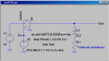
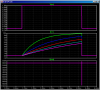
LTspice is a godsend for this sort of thing, but with a capacitor across a voltage source, whatever sudden increase in load current I apply, it appears on the supply current, capacitors don't seem to make a difference in any circuit, regardless of my voltage source impedance.

So.... any takers?
 
You don't seem to know how an inductor behaves.

If you connect a fixed voltage to a static inductor with some finite winding resistance at time t=0, the initial current is zero, and it ramps up with a **broken link removed**. If the fixed voltage is applied for a predetermined time, the current at the end of the period says something about the inductance. It would take an infinite voltage to suddenly establish a fixed current in an inductor.

Look at the plots. Top pane shows when the switch is closed.
Middle pane shows the current in the inductor.
Bottom pane shows what happens when the switch opens (Yes, units are in millions of volts, can you say Snubber Diode?)
 

Attachments

  • DF174a.png
    DF174a.png
    15.9 KB · Views: 297
  • DF174b.png
    DF174b.png
    30.3 KB · Views: 276
Last edited:
Mike, thanks for your reply, perhaps I didn't explain myself properly.

What I am trying to do is impose a fixed voltage (thus the regulated output from the cap bank) across and inductor, so the current rises linearly, as you said. Instead of measuring the current after a fixed time, its jst easier to use a current sense resistor and comparator to detect when the current through the inductor reaches a certain level. The time taken to reach this gives us 't'. As we fix V and I, we can then work out L. I can also measure saturation current by either incrementing the current limit, each time measuring L, until the inductance falls by a certain amount, or just by seeing a rise in di/dt (sharp increase in gradient) when set to a high current limit. Once limit is reached, I'll switch off the 'switch' (in this case a N channel MOSFET) and the inductor's current can flow through a diode.

I am fully aware of how an inductor works :) I was just asking about using a capbank to provide a high current for a short period of time, and somehow regulating this to < 5V preferably 2V to give me more time to measure the period between start and the current limit. A linear regulator with an opamp/pass transistor might work, but it seems a little crude, and perhaps would require a fast opamp to provide the voltage across the inductor quickly (as to not screw up results for low inductance values).

I could of course be over thinking this. It just seems if I have say a 5V power supply, with 10000uF across it, then turn on my MOSFET, unless the power supply can provide the current I'm planning on letting the inductor ramp to, the voltage will sag, warping results (as V no longer becomes fixed).
 
...I was just asking about using a capbank to provide a high current for a short period of time, ....

But if you are going to switch off the voltage source before the current gets very large, why do you need a capacitor bank? Just pick a current limit (like 1A) where you shut off the voltage source. 1A is within the current range of a simple regulator, like a LM317. Besides, a lot of inductors will saturate at currents much less than a few A, so during testing for inductance, you should be limiting the current to <1A.
 
...Instead of measuring the current after a fixed time, its jst easier to use a current sense resistor and comparator to detect when the current through the inductor reaches a certain level. The time taken to reach this gives us 't'. ...

Isn't that "measuring the current"?
 
Good call on the lower current limit but that brings its own problems. For a sensible current limit of 1A, using a power supply of say, 2V, a 4.7uH inductor would reach this current in 2.35us. Considering I am measuring 'time', that really is quite short to get any sort of resolution. An AVR's timer could capture that with a 20Mhz clock. 2.35u/50n = 47. Although that is probably the lowest inductance I will be measuring. And perhaps I could always lower the voltage even further to 1V when a low inductance is detected. Any delays in the comparator used should be more or less fixed, and so can be subtracted from the result. Even so, it starts to get 'tight', thus my use of low voltage.
As a microcontroller system there are all sorts of tricks we can do using ADC's and PWM to get a very low regulated voltage, averaging etc..

Yet another point is the use of lower voltage means that the voltage drop across the MOSFET and current sense resistor becomes more siginificant. So its a comprimise between voltage, current limit to get enough time to get half decent accuracy. High current limit gives me more time to measure, with an increase in resistor/MOSFET Vdrops, and lower voltage also increases these. Perhaps some clever high speed counters are required to keep things at sensible levels. I'm onyl really after 5% accuracy, perhaps 10% as inductors vary anyway.

Also, I will have set current limits, each time measuring the time taken for the current to reach that value. Starting at perhaps 100mA, moving up to my 'upper limit'. Another thing I was hoping to achieve is getting a rough idea of saturation current. Given it will be mostly used for my own wound transformers inductors (mostly ferrite, low resistance windings, no iron cores here) the saturation points are likely to be up to 6A. max. Certainly 3A. In order to get a fairly good idea of saturation current, one must also know the inductance at that current - which requires a stable voltage. That is unless I just look for a sharp increase in di/dt (opamp differentiator -> comparator should do) not accuracte though.

So, as you can see it can quite easily balloon in complexity once one gets an idea of what exactly will be measured. Although the limits are fairly narrow. L = 4.7uH to 10mH, and (rough) saturation between 0.5A and 6A. I'm sure it can be done in a low power portable instrument, but the current requirements, although for short bursts make it complicated

Isn't that "measuring the current"?
well yes, but its simply a yes/no measurement :) With a fixed time, I would have to measure (in continuous terms) the final current reached. Using an amp, followed by a peak detector, then ADC... seems more analogue than the digital method of period measurement, and so, tougher to implement.
 
At one point we were using a circuit like this one adapted for higher amperage:

Inductance Measuring Circuit

It had a choice of 1.0Ω/10Ω/100Ω power resistors or something similar and a complementary NPN/PNP stage connected to the output of an audio amplifier chip. One simply plugged in the frequency counter to measure the period and multiplied by 10/100/1000 or something like that to get millihenries at 0.05A, 0.5A, or 5A.

It worked very well. I don't know what happened to it. I think it was discarded in favor of a different and supposedly "better" circuit that measured inductance with a DC bias. Too bad the well crafted and simple to use box was replaced with the haphazardly scabbed together POS we currently have. The new one involves four pair of patch cords, two power supplies, two multimeters, a lot of arithmetic, and doesn't really tell us anything more than the old used to.
 
Last edited:
Hi cachehiker, thanks for the reply!

Interesting link, looks like a 'beefier' circuit to the method my original LC meter used. That is, using the inductor as part of an oscillator with a known capacitance, and measuring the frequency.

A meter I built, as stock:
Digital LC Meter Version 2 - VK3BHR
Original page for above meter:
**broken link removed**

Alas, like my own meter (but probably to a lesser extent) I fear it may suffer the same problem. For SMPS transformers/flybacks/coupled inductors, the second winding can change the resonance, or perhaps shift the frequency giving wildly inaccurate results. This is why I chose the rather inaccurate method of di/dt. It won't be much good for very low or very high inductance (say a range of only 4.7u to 47m) but it should also allow a rough estimate the 'saturation knee' given enough current. This can of course be performed with a basic circuit and oscilloscope, but as I mentioned in my first post... I'm tired of having to set up my scope, AND a bench 10A supply every time I just want to check something. A small, standalone, moderately accurate unit would be great.

I believe I have a good idea of the measurement process, providing a constant voltage across an inductor, and cutting off the supply once a certain current level is reached - which will be slowly incremented in stages from 50mA to 1A for inductance meansurement. And 0.5 to 8A for saturation.

My only problem seems to be using a capacitor (perhaps a super capacitor) to provide a constant regulated voltage to the inductor. I've no doubt there will be some sag in the voltage, but to maximise accuracy, I'm using a low voltage of just 2V. This means that a sag in voltage becomes more siginficant when compared to an inductor voltage of say 12V. It also means Voltage drops across a current sense resistor and MOSFET switch must be minimised, or perhaps eliminated entirely by putting them inside the voltage regulation loop.

So, I have seen some app notes on using supercaps (or just 'large value' capacitors) for powering 'flash LEDs' in mobile phone cameras, using the supercap for a high current pulse - but these are constant current discharges. I require constant voltage disharge. So far I have a simple opamp-based linear regulator in LTspice, with a high current NPN darlington. A 12V 2200uF capacitor powers this, and it regulates down to 2V. Getting it to hold regulation when one suddenly draws up to 10A is tricky, but seems the cheapest and easiest way.

Any idea's on how fast transient voltage regulation is done at these currents? We're talking pulses of <500uS and with the input-output differential of a linear reguator being 12V to 2V the capacitor can discharge significantly before regulation is lost.
 
For SMPS transformers/flybacks/coupled inductors, the second winding can change the resonance, or perhaps shift the frequency giving wildly inaccurate results.

Inaccurate? Are you out to construct a mathematical model for the transformer? Resistance on each winding, primary current (and hence inductance) at the frequency of interest with the secondaries open circuited, and finally primary/secondary currents (and hence inductance) with each secondary short circuited at about half the intended primary voltage?

I'd use a sine wave generator or variac, multimeters, and possibly a power amplifier in that case. Most any cheap, dedicated, high amperage inductance meter would seem too application specific. Ours was specifically designed to rapidly characterize certain sizes and types of motors and chokes and wasn't much good for switched-mode transformers and the like.
 
Last edited:
Well no, I am simply trying to create a resonabley accurate 'box' to measure the inductance of power inductors and transformers. So far, the two mthods I have used (LC oscillator frequency, and point resonance frequency sweep) work fine for most inductors, but not for flyback transformers, or forward transformers for that matter. I do not know exactly why this is.

When the other winding on the transformer I am measuring is shorted, I get a very low reading, I assume that is 'leakage inductance' between the windings. Note: I purposefully avoided saying 'primary/secondary', although the 'outer winding' (secondary usually) seems to give more accurate results with my meter, than the outer winding. The idea of also measuring saturation current is just an 'add-on' that I might as well use since I'm going to pulse with moderate current anyway.

Can you explain further what you mean in your statement? I cannot claim to be an expert in transformer theory, mostly practical applications (in that I have wound transformers and designed half bridge forward converters, flybacks, boost and buck, along with sepic).
 
Last edited:
the low reading you get when a winding is shorted is because of the mutual inductance to the shorted winding, and now your "primary" is acting like a short because the shorted turn "reflects" back into the "primary" an equal current (actually slightly less than equal, but close enough). reading the winding with all other windings disconnected and open circuit is about as close as you're going to get to an accurate reading. measuring while the other windings are connected to anything will give you strange readings. one method i use for reading inductance is to put a known capacitor in series with the winding, put an oscope at the junction, and feed the series combo with a square wave function generator. when i find the frequency where i have sine waves across the capacitor (and peak voltage) that's the resonant frequency. with a known resonant frequency and known C, i find XC, which will be equal to XL, and then solve for L also you will see if the other windings are interacting, and how much they interact because you can see it on the oscope at other frequencies where it seems to be going to resonante, but never does.
 
I do not know exactly why this is.

It's literally because any secondary connection will in effect end up in parallel with the primary as far as any measurement circuit goes.

**broken link removed**

Rp and Rs can be measured with a multimeter.
The ideal transformer is for illustrative purposes and contributes no inductance.

With an open secondary, the core losses, Rc, can then be established by measuring amps, volts, and power at the rated frequency. The reactive losses, Lp, and magnetizing current through Lm can be established by measuring amps, volts, and power at a second frequency, i.e. 50 Hz instead of 60 Hz. You then short the secondary and derive the rest with the primary voltage reduced to a level where the rated secondary amperage is flowing.

The above schematic can usually be simplified further for larger power transformers. In many cases, only Lm, Rp+Rs', Lp+Ls', and Zl' are needed and can be derived with one open secondary and one shorted secondary measurement. Rs'=(N/M)^2*Rs, Ls'=(N/M)^2*Ls, and Zl'=(N/M)^2*Zl. I doubt this applies to flyback and other switched-mode transformers though.

Rp, Rs, Rs', Lp, Ls, and Ls' are all small values so shorting the secondary results in a short circuit in parallel with the primary and hence a ridiculously low value for Lm which is generally a large value. Transformers would not be the least bit efficient if the series elements were large or the parallel elements were small.

This model can even be extended to induction motors via a little bit of mental masturbation. Zl then represents a mechanical load instead of an electrical load.
 
Last edited:
Oh wow, thank cachehiker for a detailed explaination!
I knew I would have to face an 'ideal transformer' at some point :) Although I have no aversion to mathematics (its a given in electronics obviously) because I built my L-meter relatively cheaply, I accepted any limitations rather than investigate.

And unclejed, thanks for your input! When I said my measurement of flybacks and transformers are wildly inaccurate, I meant with the secondary open (as mentioned in my previous post...in amongst the waffle).

As an example. Before winding the secondary on a slightly gapped small ferrite E-core: I measured a stable 109uH with 20 turns. My target value was 100uH, and had to gap the core further to achieve the 109u figure. When the secondary (roughly 230 turns) was wound, the measured primary inductance (on my meter) became 370uh or so. The secondary was 15.2mH.

A quick bit of maths, L/(turns^2). Primary as 109u/20^2 = 0.273uH/turns^2. The secondary measured as 15.2mH, for 230 turns, its inductance should be around 14.4mH - not that far off.

While I could attempt to modify my LCR meter to work 'better' for low inductance power ferrites (SMPS transformers, 50kHz to 500kHz) it appears to work fine for iron core power transformers, despite its high frequency operation. So, after a few spice simulations I think I'm going to stick with my original method in the starting thread: low duty cycle pulsing. Either measuring time taken to reach a given current, or perhaps (!) using a peak detector, and driving with very low duty cycle PWM, slowly increasing the ON-time and check for a linear correlation in peak current.

I believe I have found a suitable solution to a high peak current source, with regulated voltage. Large cap bank followed by a high speed opamp controlled linear regulator (thanks to Zetex and their high current, high gain NPN's). Much testing is needed because LTspice can't tell the whole story. Not to mention the AVR software I need to write. No doubt I will come unstuck with another part of this project, and post here :)

Thanks for the replies guys. Not only did it help me, but should help others.

Blueteeth
 
Status
Not open for further replies.

New Articles From Microcontroller Tips

Back
Top