Continue to Site

Welcome to our site!

Electro Tech is an online community (with over 170,000 members) who enjoy talking about and building electronic circuits, projects and gadgets. To participate you need to register. Registration is free. Click here to register now.

  • Welcome to our site! Electro Tech is an online community (with over 170,000 members) who enjoy talking about and building electronic circuits, projects and gadgets. To participate you need to register. Registration is free. Click here to register now.

Voltage Protection Circuit

Status
Not open for further replies.

jnnewton

Member
Hello,
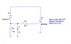
I started designing a power protection circuit and it became a side note of another thread, but i think that it is time to give it it's own subject and thread and this will maybe help some other people as I trial and error my way through this. Anyway, I am trying to protect the input to a smps (24V) from any voltage over 26ish volts up to and including 120VAC. The first circuit I tried is below (powerprotection.jpg). This did not work for 120V and I believe it to be that the TVS diode's clamping voltage was less than 120V. The problem is that I could not find a TVS diode with a breakdown voltage of around 28V with a clamping voltage of over 120V. Scrapped that design.
After some research, i came to the standard "crowbar" circuit (powerprotection2.jpg) And I think that this could work. Here is what i have so far, but am a little unclear about how to choose some of the components:

B1 - Rectifier in case someone puts AC voltage on the input
Type - Schottky, Schottky Silicon Carbide, Avalanche or Standard
?? (Doesn't Matter??)
Current Rating - Greater than the fuse Rating (1A)
Voltage Rating - At lease the maximum voltage to protect against (120V)
Speed - ?? (Doesn't Matter??)
Reverse Recovery Time - ?? (Doesn't Matter??)

F2 - Blows to protect Circuit
Type - Fast
Current Rating - Slightly Greater than Current draw of System Being protected (1A)
Voltage - minimum 2x maximum protected voltage (120V)
I2t less than I2t of SCR

C10 - Reducing Input noise
Capacitance - 100uF used in past seemed to work
Don't know if this will work in this case or not. Can try different types
Voltage - Greater than max protected voltage (120V)
Type - Electrolytic
D4
Breakdown Voltage - Slightly Greater than the normal working voltage (26, 27,28V)
Reverse Current - Greater than the draw from SCR and R12 (in parallel at breakdown) (???)
Power - Reverse Current x Max Voltage (???)
Max Voltage - Greater than the max protected voltage (120V)

R12 - provides current to the gate of the scr when D4 breaks down, current flows from + through D4 to SCR and through resistor to ground
Resistance - (???)
Power - (??)

C11 - Prevents thyristor from being triggered at power on. (called snubber)
Capacitance - High enough to snubb D4 (), Low enough not to create high state at the gate at power on. (??)
Voltage - Greater than max Voltage at SCR Gate which will be max protected voltage ( > 120V)
Type - (???)

D6 - SCR
Voltage Rating - Higher than the max protected voltage (120V in this case)
Current Rating - Higher than the Fuse rating (1A)

To Do:
Select SCR, then R12, then D4, then we can just try C10, C11.

SCR: MCR12DSMT4G (ON Semi)

Let me know if I am way off track here and if you have any suggestions, let me know. I will update this as I go for anyone who has the same problem in the future.
 

Attachments

  • Power Protection.gif
    Power Protection.gif
    10.1 KB · Views: 374
  • powerprotection2.gif
    powerprotection2.gif
    8.1 KB · Views: 315
Ok, now i am stuck. Supposedly the resistor acts as part of a voltage divider circuit with the Source impedence in order to provide the correct voltage to the gate of the scr. What if I don't know the source impedence because I don't know the source. The idea is to protect from unknown inputs, so is there an assumption normally used that i haven't seen in my searches?
 
The first circuit I tried is below (powerprotection.jpg). This did not work for 120V and I believe it to be that the TVS diode's clamping voltage was less than 120V. The problem is that I could not find a TVS diode with a breakdown voltage of around 28V with a clamping voltage of over 120V. Scrapped that design.

huh??? whether you put 28V or 120V the TVS conducts and keep the voltage at ~ 28V. The idea is that it short the unkown input supply for a long enough time so that the fuse blows and then holds off the input voltage.


jnnewton said:
Ok, now i am stuck. Supposedly the resistor acts as part of a voltage divider circuit with the Source impedence in order to provide the correct voltage to the gate of the scr. What if I don't know the source impedence because I don't know the source. The idea is to protect from unknown inputs, so is there an assumption normally used that i haven't seen in my searches?

put a series resistor (on right side of capacitor) in the SCR gate.. then you can also have a zener from gate to ground to keep gate voltage clamped. Put the additional zener on the right side of the resistor so it benefits from the resistors current limiting.
 
Last edited:
The idea is that it short the unkown input supply for a long enough time so that the fuse blows and then holds off the input voltage.

Right, except the TVS quit working properly (conducted all the time, even below the 30V it was rated at.) Is this (the first circuit) even viable, and is the second a better choice?

put a series resistor (on right side of capacitor) in the SCR gate.. then you can also have a zener from gate to ground to keep gate voltage clamped. Put the additional zener on the right side of the resistor so it benefits from the resistors current limiting.

Done(see schematic).

I need some information on how to calculate all of the values of the components. Specifically what to look for based on the design criteria (operating voltage, load current, max input protection, etc.). I want to be able to build this circuit regardless of the design parameters. I understand the theory behind how this is supposed to work, but don't know how to choose all of the components to test.

1. there are about 5 voltages and current parameters for zener diodes depending on the voltage applied, which ones do i need to be looking for?

2. what is the current rating needed for the scr. It will open between power and ground, how much current will flow.
 

Attachments

  • powerprotection3.gif
    powerprotection3.gif
    9.8 KB · Views: 275
I put the diode backwards. it should regulate the input voltage to the SCR. If the voltage at the gate is always say one volt, how do i limit the current to the gate to less than 4 A but greater than 2 mA. the current is going to flow through the resistor and breakdown the diode right? I need an example with numbers so i can see how the values change at different input voltages based on the components. Does anyone have an example they would be willing to share?

how do i choose the wattage of the zeners? should they be tvs? what determines how much current flows into the gate of the scr? what is reverse gate voltage? should the top be rated at 26 or breakdown at 26 or clamping 26? I cannot find the definition of clamping on the web. I know it is larger than the breakdown, but what it is used for???? will the voltage at the resistors be the same as the input voltage when above the breakdown voltage of the top zener? How can i find the ratio of current flowing through the bottom zener and the gate of the scr?

sorry, and i appreciate the help so far, just a little confused and a little frustrated.
 
You don't need the zener on the gate. The gate is basically a diode, and if the voltage gets high enough to cause that zener to conduct, your SCR is already toast.
You're trying to protect against >26V. What is the operating voltage?
For your SCR current rating, don't forget it has to survive the peak transient current during the discharge of your filter cap.
 
Operating voltage is 24Vdc.
Problem voltage is mains 110-132ish VAC

I found an scr from STMicro that has a voltage rating of 1000 V and will conduct 16A peak. I chose it b/c it is available in both smt and th and I have another idea for the part. I hope it will work. part no is TN1625-1000G

Thanks for the reply Roff...by the way, parts for your suggested op amp circuit will be here soon. ( I don't think I thanked you yet for that one.)

Do you know (for my own education) what the difference between the breakdown voltage and the clamping voltage for a tvs is? I fried one yesterday trying to just use it for this, worked for reverse voltage, but 120VAC turned it into a fancy wire.
 
Just a note - your bridge will drop about 1.4V, so the output voltage is around 22.6V.
Do you know (for my own education) what the difference between the breakdown voltage and the clamping voltage for a tvs is? I fried one yesterday trying to just use it for this, worked for reverse voltage, but 120VAC turned it into a fancy wire.
Look at this chart (these are quad parts, which you don't need). It should be self-explanatory, but for example, look at the 27V part (MMQA27VT1). The breakdown voltage is nominally 27V @ 1mA. The clamping voltage is 39V @ 615mA.
Keep in mind that I have never used a TVS. I'm just interpreting the datasheet.:eek:
 
I used a very similar chart and chose the tvs based on the breakdown voltage very similar to the one you pointed out. what happened was that the tvs fried at 120V and i think it was because 120V was greater than the clamping voltage. .. But anyway, i removed the diode, and then calculated my values as follows for the crowbar circuit:

1. at the breakdown voltage, d4 conducts, bringing the high sides of R12 / 14 to 120V max. now these are selected at 100k. I too the gate voltage divided by the gate current to get the gate resistance of the SCR to be 52 ohms (Rg).

2. R12 is in parallel with the R14/SCR combo and has a 120V drop across it when the diode breaks down

The problem is that with the resistors this way, the current into the gate is 1.2mA when the pwer dissipated by d4 is under 1500mW (about the biggest one i can get in smt and th at 25-27VDC.

Am I on the right track here? No, it is 1500 W. Alright, i am going to give this a try, but i don't think i will use a full rectifier, if i just put a diode in parallel i can blow the fuse if it is ac or gets hooked up backwards.
 
Last edited:
If you use a sensitive gate SCR, you can also use a low power zener as below.
 

Attachments

  • crowbar.PNG
    crowbar.PNG
    9.6 KB · Views: 375
Connect the circuit's 0V to protective earth amd make sure the mains circuit has an RCI (I think you anks call it GFI). That way your circuit only needs to stand 30mA (or whatever current your earth protection system trips at) for a very sort time.
 
Hero999 said:
Connect the circuit's 0V to protective earth amd make sure the mains circuit has an RCI (I think you anks call it GFI). That way your circuit only needs to stand 30mA (or whatever current your earth protection system trips at) for a very sort time.
Good idea, Hero.
He still needs the fuse in case someone connects a DC source or a transformer-isolated AC source to the inputs.
 
Yes that's true.

A fuse in the DC side would also protect it from a DC to neutral short.
 
Thanks everyone. What are the chances this will work fine without the GFI or the protective earth? I ordered parts for roff's circuit and they will be here on monday.
 
jnnewton said:
Thanks everyone. What are the chances this will work fine without the GFI or the protective earth? I ordered parts for roff's circuit and they will be here on monday.
It should work without the GFCI and earth connection.
 
It will work without the GFCI and earth connection, it just won't be very safe.

If the live gets bonded to the DC then it will pose a shock hazard and you won't know about it.

For safety's sake you really do need either one or the other but both are best. If you don't earth bond it then the GFCI will cut out if the live contacts the DC side and you touch it. If you earth bond the DC side then a fuse will blow if the live comes in to contact with it. Both earth bonding the DC side and using a GFCI on the AC side is best as it means the power will be turned off if the mains touches the DC side, no fuse will blow and there will be no chace of you getting a shock, even if either the GFCI or fuse fail to trip.

The best way of solving this problem is to design your project so the DC side is double insulated from the mains, that way there's no chance this sort of thing can happen.
 
Status
Not open for further replies.

New Articles From Microcontroller Tips

Back
Top