Continue to Site

Welcome to our site!

Electro Tech is an online community (with over 170,000 members) who enjoy talking about and building electronic circuits, projects and gadgets. To participate you need to register. Registration is free. Click here to register now.

  • Welcome to our site! Electro Tech is an online community (with over 170,000 members) who enjoy talking about and building electronic circuits, projects and gadgets. To participate you need to register. Registration is free. Click here to register now.

Voltage oscillations due to digital current meter

Status
Not open for further replies.

po210

New Member
Hello
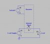
For my power supply project I have a Digital current meter like this

**broken link removed**

working from this isolated power supply module

**broken link removed**

It reads current well, but when connected I can see big voltage peaks (+-150mV) with some fixed period.With oscilloscope I see peaks are in fact dumped oscillations.
Has somebody seen same effect? Do you know how can I get rid of it?. Or is this a general "feature" of this kind of meters?
Thank you
 
Where do you see the damped oscillation?
In what the meter reads numerically?
In the isolated power supply that runs the meter?
 
Where do you see the damped oscillation?
In what the meter reads numerically?
In the isolated power supply that runs the meter?

I see the oscillations in the output voltage.They dissapear if the amp meter is out.The meter read amps, and is constant.
 
I see the oscillations in the output voltage.They dissapear if the amp meter is out.The meter read amps, and is constant.

You mean that the voltage fluctuation can be observed on the load-side (R2 in the attached figure) of the ammeter?

What is supplying the Load Supply that drives the load?

The isolated power supply that powers the ammeter is truly isolated from ground?
 

Attachments

  • Ammeter.jpg
    Ammeter.jpg
    43.3 KB · Views: 122
Last edited:
Yes.The current through the ampmeter feeds a load at a voltage. The output voltage is produced basically with an op amp with a transistor in its negative feedback regulation loop. the oscillations appear only when the ampmeter is in the load-side.
 
Sounds like the shunt resistor inside the ammeter adds just enough resistance to make the opamp circuit unstable. Measure the resistance between the big red and black wires going into the ammeter module. It should be low, much less than 1Ω. Either the ammeter is bad (open shunt), or your opamp circuit is marginally unstable...
 
oopps...
I´ve just measured the output of the isolated power supply module that feeds the ampmeter (the one in the link at first post) with the oscilloscope and I see the oscillation comes from the module. I know inside this thing there are some typical commutation power supply / oscillating circuits but peaks of 150mV in its output over the output voltage is... VERY bad.
How can I minimize thar? Will a small TO92 LM317 linear regulator after the ouput reduce the peaks?.
 
Last edited:
oopps...
I´ve just measured the output of the isolated power supply module that feeds the ampmeter (the one in the link at first post) with the oscilloscope and I see the oscillation comes from the module. I know inside this thing there are some typical commutation power supply / oscillating circuits but peaks of 150mV in its output over the output voltage is... VERY bad.
How can I minimize thar? Will a small TO92 LM317 linear regulator after the ouput reduce the peaks?.

Substitute an isolated wall-wart (plug-pack) that puts out the requisite DC voltage for the "isolated" supply from ebay. I'll bet that will have better regulation.

Question is, are you allowing a sufficient time for the isolated supply to stabilize after turn-on, or are you somehow switching it on just before making the measurement?
 
Status
Not open for further replies.

Latest threads

New Articles From Microcontroller Tips

Back
Top