Continue to Site

Welcome to our site!

Electro Tech is an online community (with over 170,000 members) who enjoy talking about and building electronic circuits, projects and gadgets. To participate you need to register. Registration is free. Click here to register now.

  • Welcome to our site! Electro Tech is an online community (with over 170,000 members) who enjoy talking about and building electronic circuits, projects and gadgets. To participate you need to register. Registration is free. Click here to register now.

Voltage jumps for port A

Status
Not open for further replies.

rngd

New Member
Hi all,

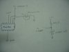
Regarding port A, why is it when I connect a low voltage into it from a photodiode, the voltage of the photodiode (and so the voltage at the pin) increases ? The open circuit voltage is 0.25V, and when I connect to AN0 it increases to 0.48V ?
The photodiode negative is connected to gnd and positive to the pin.

When I connect the variable voltage on my programmer board the voltage at pin also increases (tried for 0.6V, 1V, 2.5V). But when I connect voltage from a LM385-2.5 voltage reference it does not increase.

Is this a common occurrence with port A/PICs ? Anyone have any clue ? Im using PIC16F877A.

Thank you all.

edit: this happens with all the channels of port A. When nothing is connected, all pins of port A is at +5V.
 
Last edited:
Hi Nigel, thanks for the reply. Im programming in PICBasic Pro. Here is the code Im testing

define OSC 20
define ADC_BITS 10 'define number of bits in result
define ADC_CLOCK 3 'clock source3=RC
define ADC_SAMPLEUS 50 'set sampling time in microsec

m1pos var portd.7 'to motor 1 positive
m1neg var portd.6 'to motor 1 negative
led1 var portd.3

tolerance var byte
adc1 var word
adc2 var word
diff var word
lowlimit var word

trisa = %11111111
trisd = %00000000

adcon1 = %10000011
pause 500


duration = 1000
tolerance = 8
lowlimit = 82

pair1:
adcin 0, adc1
adcin 1, adc2
diff = abs(adc2-adc1)
if (adc2 > adc1) and (diff > tolerance) and (adc2 > lowlimit) then
high m1pos
low m1neg
high led1
pause duration
low m1pos
low m1neg
low led1
pause duration
pause 10
goto pair1
else
low m1pos
low m1neg
pause 10
goto pair1
endif

So its a software problem ?
 
Last edited:
Its probably because you are using 2 channels on the ADC and the photo diode is a high impedance source (should be less than 2.5k:eek:hm:). What is happening is that the charge from your variable ADC input is being transfered to the photo diode ADC input by the PIC internal Chold capacitor because the ADC is scanning between these two inputs.
Solution: buffer the photo diode with an OpAmp.
 
Thanks a lot kchriste ! Yea, that must be the problem.

What are the common quad opamp ICs that are used as buffers ? I need it to be sensitive to low voltage inputs (~0.20V-0.50V). Will the LM339 do ?

By the way, that portion of the code has 2 analog inputs but my whole program will have 4 analog inputs.

Thanks again.
 
bananasiong said:
Isn't 339 a comparator ic? Maxim and TI have a lot of op amp.

Oh OK, did some reading and the LM339 only outputs in binary states (I always thought comparators were just a type of op amp and so were the same thing).

Are there certain op amp ICs that are more suitable as buffers than others, or can anyone be used ?
 
rngd said:
Are there certain op amp ICs that are more suitable as buffers than others, or can anyone be used ?
Since photodiodes usually convert light into current, you could build an I/V converter. J-FET op amps with low input bias current are suitable for this task. I would suggest reading some documentation about photodiode amplifiers, there are a lot of examples.
 
Last edited:
eng1 said:
Since photodiodes usually convert light into current, you could build an I/V converter. J-FET op amps with low input bias current are suitable for this task. I would suggest reading some documentation about photodiode amplifiers, there are a lot of examples.

Actually, Im quite happy with the low voltage that the photodiode outputs right now, without having to add any amplifiers/build anything extra. I just want to be able to get that voltage into the PIC analog pin.

edit : Ill probably go with the LM324 IC ?
 
Last edited:
rngd said:
edit : Ill probably go with the LM324 IC ?

Why chooose a quad opamp at all?, never mind the lowest spec one you could find.

Try the Texas TL0x1 series, far better devices, and available as dual or quad if you really want.
 
Nigel Goodwin said:
Why chooose a quad opamp at all?, never mind the lowest spec one you could find.

Try the Texas TL0x1 series, far better devices, and available as dual or quad if you really want.

I chose quad because Im using 4 photodiodes and four analog pins. Heh, I did not know they were the lowest spec, I just Googled for op amps because Im unfamiliar with ICs.

Any others other than the TL0x1 in case I cant get them ?

Thanks for the replies.

edit: I found the TL034 (for quad).. What is the advantage of this IC over the LM324 ? Higher precision ?
 
Last edited:
I'm not sure about a TL034?, but the TL074 and TL084 are excellent devices, compared with an LM324 they are much higher gain, much higher bandwidth, much lower noise, and much higher impedance inputs.

If you were talking cars, the TL series are like a modern hatchback, Voltswagon Golf GTI, something like that? - the LM324 is like a model T ford with three flat tyres! (and this is probably an UNDER exaggeration!).
 
heh, nice analogy ..

OK, so I bought the TL084 and connected it as a voltage follower. However I cannot get equal voltage at the output if I input the photodiode voltage (around 0.30V). The voltage can follow if I connect 2.5V. I tried simulating it and it seems the output can only follow the input when Vin >= 1.8V, even though the datasheet states Vin 'must never exceed magnitude of supply voltage or 15V, whichever is less' ?

Is the voltage too low ? I have Vcc+ connected to 5V and Vcc- to ground.
 
Last edited:
Nigel Goodwin said:
Draw the diagram how you've connected it, and post it here, so we can see what you're doing.

Here you go. The right part is just for the 2.5V Vref+.
 

Attachments

  • IMG_0248.jpg
    IMG_0248.jpg
    589.6 KB · Views: 153
Nigel Goodwin said:
You don't appear to have it connected at all like an opamp should be, feedback is really pretty essential.

Check this link for a design tool

Isnt it just a buffer/voltage follower if I want to have the Vout from the opamp the same as the Vin, with gain 1 ?
 
The output from a photodiode is absolutely tiny, you need to amplify it, and is current rather than voltage, the link I posted gives the circuit for converting the current to voltage.
 
Nigel Goodwin said:
The output from a photodiode is absolutely tiny, you need to amplify it, and is current rather than voltage, the link I posted gives the circuit for converting the current to voltage.


OK, i read up a bit on the photodiode amplifiers and those I-V converters.. But with my deadline coming, I decided to just swap the photodiodes with LDRs instead to uncomplicate things. Thanks for all the help anyways, Nigel and all those replied. :D
 
Status
Not open for further replies.

Latest threads

New Articles From Microcontroller Tips

Back
Top