Continue to Site

Welcome to our site!

Electro Tech is an online community (with over 170,000 members) who enjoy talking about and building electronic circuits, projects and gadgets. To participate you need to register. Registration is free. Click here to register now.

  • Welcome to our site! Electro Tech is an online community (with over 170,000 members) who enjoy talking about and building electronic circuits, projects and gadgets. To participate you need to register. Registration is free. Click here to register now.

Voltage doubler confusion

Status
Not open for further replies.

carbonzit

Active Member
OK, I know how a voltage doubler works ... or do I? Rereading the explanation of its operation, there's something I just cannot wrap my brain around.

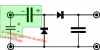
So this, as we all know, is the classic voltage doubler circuit:

**broken link removed**

All the explanations invariably start with this: on the first negative cycle on the input, the first (leftmost) diode conducts, charging the leftmost capacitor with the polarity shown:

**broken link removed**

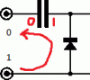
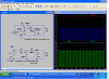
But here's where it goes off the tracks for me. Now the first positive-going cycle comes. But isn't it going to be in opposition to that charged capacitor?

**broken link removed**

Look at the way the capacitor charges on the negative cycle: the capacitor plate closest to the positive terminal, the rightmost plate, gets a positive charge. Right?

So now when the positive cycle comes, it's going to want to charge the plate closest to the positive terminal--the leftmost plate--positively. Am I right? But that plate already has a negative charge, not a positive one. So instead of doubling the charge, shouldn't it just cancel it out to close to zero?

I must be missing something really obvious here, since it's well known that this circuit actually works. So what am I missing here?
 
Last edited:
The voltage source and the leftmost cap act like two voltage sources in series, wich gives twice the voltage.
 

Attachments

  • Voltagedoubler3.png
    Voltagedoubler3.png
    6.3 KB · Views: 284
The cap and power supply are series aiding when the polarity changes. This doubles the voltage, the supply voltage and the voltage across the cap, and as the current can't flow through the left most diode the total voltage forms across the second cap.
 
But here's the source of my confusion. Let's take the case of a single diode followed by a capacitor:

**broken link removed**

That is how the capacitor will be charged, correct? But that's the opposite of how the capacitor is charged on the negative half-cycle above. So I still don't understand how the two voltages can add. Grossel's diagram sort of helps, but I still don't get it.

I should point out that while I'm a smart person, I have problems with simple things like this. For instance, it still hurts my head to try to figure out exchange rates, and whether it's better for us (here in the U.S.) if the dollar is weaker or stronger than other currencies. (I know, it depends, but the point is that it's difficult for me to keep simple binarydirections--up/down, higher/lower, positive/negative--straight.)
 
Last edited:
Assuming a 10V/0V and 0V/10V signal to the terminals on the left.

In the first half cycle, you've shown the rhs of the cap gets charged through the diode to 10V. Now in the next half cycle the lhs of that cap is at 10V - if you ignore the other components, so it's just the power supply and the cap then the cap won't discharge - so the rhs of the cap is 20V as the cap still has 10V across it (as it wasn't allowed to discharge).

If the cap can discharge - e.g. through the other diode - it will do so, and some of the charge will be transferred to the second cap. Eventually the second cap will have 20V across it.
 

Attachments

  • s1.gif
    s1.gif
    2 KB · Views: 244
  • s2.gif
    s2.gif
    1.6 KB · Views: 246
  • s2a.gif
    s2a.gif
    2.5 KB · Views: 239
Thanks, but sorry, still doesn't do it for me.

Explain what's happening in terms of polarity; that's what's bothering me here.

You say

so the rhs of the cap is 20V as the cap still has 10V across it (as it wasn't allowed to discharge).

But that assumes that the incoming charge has the same polarity as the existing charge on the capacitor, right? Otherwise, the voltages couldn't add.

It still looks to me as if the polarity of the positive half-cycle charge is the opposite of the existing charge from the negative half-cycle.
 
Here is a different approach.
1).Start off with CLeft and Dleft only. Replace Dleft with a resistor. Input is 0/10V. Across the resistor is +5/-5 because the cap will block the DC.
2).Input 0/10V, Cleft and Dleft only. Assume the diode is not perfect. It leaks a little current and has 0.7 volts forward drop. The signal across the diode will be -0.7 volts/+9.3V. This because the diode turns on when driven negative and thus peak detects the most (-) part if the signal at =0.7V.
3.)With all the parts in place; Dright will conduct only during the most positive part of the (-0.7V/+9.3V) signal. Any time the signal, where the diodes touch, hits +9.3 volts Dright conducts and pulls Cright up to 8.6V.

There fore the output is roughly (Vin peak to peak) - 1.4 volts.
There are some loss in the caps.
 
Voltage doubler vs. Charge pump

I'm wondering if you are confusing a voltage doubler with a charge pump?

Note the negitive pulse on the voltage doubler input.
 

Attachments

  • chgpmp.PNG
    chgpmp.PNG
    78.3 KB · Views: 229
Last edited:
RonV,
Try your top circuit for more cycles and with a load on the output. Just to be equal, also do the bottom circuit.
 
But that assumes that the incoming charge has the same polarity as the existing charge on the capacitor, right? Otherwise, the voltages couldn't add.
The voltages across series-connected components always add. Please refer to Kirchhoff's voltage law.
 
The voltages across series-connected components always add. Please refer to Kirchhoff's voltage law.

What about this pair of series-connected charged capacitors? Wouldn't their net voltage (assuming equal charges) be zero?

**broken link removed**
 
Last edited:
Any series-connected components, so "Yes" to "What about this pair...".

If you flip the left capacitor in the image you just posted, what is the voltage at each junction?

If the left [flipped] capacitor is replaced by a voltage source (as it is for your voltage doubler circuit), what is the voltage at each junction?

In both of the above cases, the capacitors are not 'charged backwards', as there is no current flow. Using the second case: If you connect the two free ends together with a resistor, you will see the capacitor discharge to 0V and continue to recharge in the reverse direction. If you connect it to some diodes & capacitors, as per your voltage doubler schematic, the same sort of thing will happen - depending on the ratios of capacitance and the existing charge on the capacitors.
 
Hi RonV,

Change V3 to 500.

Input 5volts and get 504.5volts out. Free energy! Now if we can make it work with just one wire. (sorry that another post)
 
Any series-connected components, so "Yes" to "What about this pair...".

If you flip the left capacitor in the image you just posted, what is the voltage at each junction?

Voltage with respect to what?

If the left [flipped] capacitor is replaced by a voltage source (as it is for your voltage doubler circuit), what is the voltage at each junction?

What polarity is the voltage source?

Let me just restate at this point that I'm not arguing with the operation of the voltage doubler. I know it works, and I know why and how it works.

The problem is that the explanation of how it works looks wrong to me, with respect to polarity. (You see, it's all about polarity here.)

I'm also tired of drawing diagrams, so I'd like to request that someone else draw me a diagram. Here's what I'd like explained:

Draw a positive voltage source in series with a capacitor. Show me the polarity of the charge across the capacitor (obviously after some time has passed and the capacitor has been charged from the source).

It does matter which way (polarity-wise) a capacitor is charged, right?

Please bear with me. If I have trouble understanding this, no doubt there are other people who do as well, so this could be useful for them too. This is not just interesting but important to me, as it interferes with my understanding of basic circuit operation.
 
Last edited:
What about this pair of series-connected charged capacitors? Wouldn't their net voltage (assuming equal charges) be zero?

**broken link removed**
If the capacitors have equal capacitance and equal voltage then yes, the measured voltage between the two "+" terminals is zero.

With respect to your original question about the voltage doubler, if you are still confused, try this though experiment with ideal components and with no load on the capacitor output:

At the end of the first negative half cycle the voltage measured across the cap is 10V with the positive on the right. Since the input sinewave is now at 0V with respect to ground, then the voltage measured from the right side of the cap to ground will also be 10V.

Now proceed to the positive peak of the positive half cycle. The voltage on the left (-) side of the cap is now +10V. Since the cap has no load and has not lost or gained any charge the voltage across it is still 10V. But the voltage measured to ground from the right (+) side of the cap is now 20V since the two voltages add.

Now if you add a grounded load to the cap right side it will discharge. If you let it totally discharge then there will be +10V on the left of the cap and 0V on the right. The cap is now charged with 10V reversed polarity. (In the normal doubler operation, however, the cap is only partially discharged).

Now when the negative input is again applied the cycle is repeated.

Does all that make sense to you?
 
Hello,

Charge up two large caps with 10v each. Connect them in series. What do you get across the two? You get 20v because the cap voltages add.
The cap is like a battery for a time, so replace the first cap on the left with charged battery and go from there for that next half cycle.

Yes, the charged cap also discharges a little too as it helps to charge the second cap. It's not a perfect circuit. With a low load current drain the caps charge up quite a bit.
 
At the end of the first negative half cycle the voltage measured across the cap is 10V with the positive on the right. Since the input sinewave is now at 0V with respect to ground, then the voltage measured from the right side of the cap to ground will also be 10V.

Now proceed to the positive peak of the positive half cycle. The voltage on the left (-) side of the cap is now +10V. Since the cap has no load and has not lost or gained any charge the voltage across it is still 10V. But the voltage measured to ground from the right (+) side of the cap is now 20V since the two voltages add.

OK, so maybe that helps a little.

So what's happening is that even though the now-positive voltage is actually charging the capacitor in the opposite polarity to the previous negative half cycle (right?), the incoming charge "lifts" the total charge on the capacitor (from V to 2V). Is this correct?

I'm still confused about how you can start out with a capacitor charged thus (by the negative half-cycle)

- --||-- +

then have a positive-going charge, which wants to charge the capacitor thus

+ --||-- -

and somehow have them add.

To help my understanding, can you answer the question I posed above? If you have a capacitor charged by a positive-going cycle applied to the left side:

---||---

what polarity is it charged at afterwards?
 
Last edited:
Status
Not open for further replies.

Latest threads

New Articles From Microcontroller Tips

Back
Top