Continue to Site

Welcome to our site!

Electro Tech is an online community (with over 170,000 members) who enjoy talking about and building electronic circuits, projects and gadgets. To participate you need to register. Registration is free. Click here to register now.

  • Welcome to our site! Electro Tech is an online community (with over 170,000 members) who enjoy talking about and building electronic circuits, projects and gadgets. To participate you need to register. Registration is free. Click here to register now.

Voltage Dividing Networks

Status
Not open for further replies.
Dear All

I'm pushing my luck but can anyone advise me voltage dividing networks?

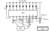
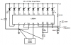
I am using an LM3914 to drive a 10-segment LED bar graph. It's very simple to connect up and if I put virtually any size of variable resistor to vary the 0-5v signal input voltage, the bar graph lights up, up and down as it should. No problem.

What I would like to do is replace the variable with a set of 10 fixed resistors.

My question is, is there a standard way to calculate the fixed resisitor values or is it done by simply measuring the value across the pot one step at a time as each segment lights up?

I don't know much about how the LM3914 works although I have the datasheet for the IC. What seems to happen is that it takes the maximum value of whatever variable resistor it's connected to and divides this up into more or less 10 equal steps. So if I use a 500 ohm pot, I get roughly 40 ohm steps between each segment lighting up. If I use a 50 ohm, the steps are about 4 or 5 ohms.

I'd be very gateful if anyone can advise.

Regards

Trevor
 
It depends on what you really want to do.

An LM3914 is intended to drive a bar graph from a varying voltage, in your test circuit that varying voltage is produced by the pot.

Do you want to:

a/ Just use a switch to produce the varying voltage instead of a pot

b/ Just light up 1 led at a time using a switch, in which case you dont need the 3914.

Sorry if this appears to be a stupid reply, but it is amazing the number of posts on here which just plain "ask the wrong question".

JimB
 
The LM 3914 has a voltage divider inside it, the junctions between resistors are connected to the inputs of voltage comparitors.

As the input voltage is increased from zero, voltage comparitors inside detect when the input passes through each voltage level and turn on the respective output.

So it does not matter what value of pot you use as it is the input voltage that is the important issue. That is why you found that a 500 Ohm pot gives the same result as a 50 Ohm one.

If you use a string of resistors you will need to be careful about the tolerance since there will be a progressive error. I suggest you use 1% resistors.

The voltage at the output of a voltage divider comprised of 2 resistors R1 & R2 in series across a voltage source of V volt is given by

Vout = V * R2/(R1 + R2)

As JimB said, what are you trying to achieve?

Len
 
Hi ljcox, JimB

Thanks for your helpful replies. Certainly not "stupid" ones. More likely my questions are! Sorry to have been unclear in describing what I want to do.

The application I'm trying to develop is a very accurate fuel gauge for a motorcycle tank and the variable resistance is part of the tank sender component. The senders on most cars and bikes have an arm with a float on it (like a toilet cystern) that adjusts a variable resistor but they are notoriously inaccurate.

The idea is to replace the pot with a set of 10 fixed resistors. They will do exactly the same job as the pot but in fixed steps - ie one resistor = 1 LED segment. Each resistor will be switched in and out of circuit by a reed switch. The reed switches will be sealed inside a stainless or brass tube mounted vertically in the tank. A doughnut-shaped float containing a small magnet will slide up and down the outside of the tube according to fluid level. I want each switch to open/close in increments of 1.5 litres since it's a 15 litre tank and I have 10-segments on the LED.

I assume that the resistors will have a cumulative value as the float goes up so for example if the total value is 100 ohms then the resistor steps would be something like 10, 20, 30 ...... 100. This is the bit I'm not sure about.

This type of tank sender is available commercially but I wanted to build my own. There's also the "capacitive" type of tube sender which is basically two tubes one inside the other with an amplifier to measure the varying capacitance as a collumn of fuel rises up between them (or something like that). I could just buy one but I'd then need a circuit to interface the amp to the LED driver and I wouldn't have a clue about doing that.

Thanks again for the help.

Trevor.
 
I don't think that what you're suggesting is going to work in the way that you want it to. If I'm understanding your idea correctly, you want to design a voltage divider which splits your 5V supply into 10 equal parts, yes? That in itself is very easy - if you design a 10 resistor voltage divider all of which have the same value (let's say, 100K) then you'll get 10 equal divisions of the 5V available at each of the 10 divider output. In this case, you'll start with 5 at the top, 4.5V at the next resistor down, 4V at the one after that, and so on until you reach ground.

But you're saying you want to switch these resistors out of circuit one at a time, as the fluid level in the tank increases or decreases. So I assume you're just going to have one output from the voltage divider (probably the top one) and, as you switch each resistor out of circuit you want the voltage at the top-most ouput of the divider to change by an equal amount. This will work to some degree, but you won't get a linear change at the output and therefore the output won't change by the same amount each time a resistor is switched out of circuit. Instead you'll end up with more of an exponential effect, so that the first resistor you switch out will only cause a drop in output voltage of perhaps a 100mV. But as you get further up the chain the change would become more apparent until finally, you get down to your last two resistors, at which point the 5V supply would be spilt in half between the last two resistors. So basically, if I understand your idea correctly it's not going to work in the way that you want. By switching out the resistors in the divider network, you change the properties of it each time.

Brian
 
Brian

Many thanks. What your saying sounds logical to my limited understanding and it's probably not going to work as you say. Either that or my description is still inadequate. I realise that part of my problem is in not describing things well enough. I was trying to avoid being long winded but obviously haven't suceeded!

I thought that I could duplicate the action of the variable resistor by splitting the total end-to-end value into 10 steps. The bit that confuses me was whether the resistors would be a linear sequence in equal steps or in progressively larger values as they go up the chain. The "wiper" connection simply gets "switched" into the network at the junction point of each resistor pair. The LM3914 would be used in "bar" mode so the first switch lights up bar 1, the second lights up bar 1 and 2, the third switch bar 1, 2 and 3 and so on all the way up to switch 10 which will turn on all 10 segments indicating a full tank.

My first attempt was to simply take a resistance measurement off the pot as each segment lit up. This seemed to indicate a fairly linear sequence of resistors - 10, 20, 40, etc. I then tried a set of 100 ohm, multi-turn variables wired in series to try and get the exact values for each segment but I got the sort of exponential effect you're describing. I may have to re-think the whole thing.

Thanks again for the reply.

Trevor


ThermalRunaway said:
I don't think that what you're suggesting is going to work in the way that you want it to. If I'm understanding your idea correctly, you want to design a voltage divider which splits your 5V supply into 10 equal parts, yes? That in itself is very easy - if you design a 10 resistor voltage divider all of which have the same value (let's say, 100K) then you'll get 10 equal divisions of the 5V available at each of the 10 divider output. In this case, you'll start with 5 at the top, 4.5V at the next resistor down, 4V at the one after that, and so on until you reach ground.

But you're saying you want to switch these resistors out of circuit one at a time, as the fluid level in the tank increases or decreases. So I assume you're just going to have one output from the voltage divider (probably the top one) and, as you switch each resistor out of circuit you want the voltage at the top-most ouput of the divider to change by an equal amount. This will work to some degree, but you won't get a linear change at the output and therefore the output won't change by the same amount each time a resistor is switched out of circuit. Instead you'll end up with more of an exponential effect, so that the first resistor you switch out will only cause a drop in output voltage of perhaps a 100mV. But as you get further up the chain the change would become more apparent until finally, you get down to your last two resistors, at which point the 5V supply would be spilt in half between the last two resistors. So basically, if I understand your idea correctly it's not going to work in the way that you want. By switching out the resistors in the divider network, you change the properties of it each time.

Brian
 
Trevor

Basically any 10 resistors of equal value, connected in series, will give you a total of 10 voltage steps between your maximum and minimum voltage.

If you then use a reed switch to send the appropriate voltage to the 3914 you will be in business.

But, there is an "ooh I never thought of that" hiding in here!

What happens when the magnet is floating at a point just between two read switches? No switches closed, fuel level reads zero.
Admittedly this is only a transient condition I guess, depending how far apart the reed switches are, just shake the bike and the fuel slopping around will sort the problem out.
Probably the easy way out of this is to put a capacitor on the input of the 3914 to hold the voltage during the periods of no contact.

There could also be the possibility of two switches being closed together, after a quick scribble, I think this will not be too big a problem in the mid-range of tank level, but at the full and empty extremes, the tank will show full when it is not quite full, and empty when it is not quite empty.

However, it practice I dont think this will be such a problem.

Good project!

JimB
 
JimB:

But the way I interpreted his design was that as the tank is filled, so each individual reed switch would be closed. If this IS the way it's designed it won't work because if, for example, the tank is half full then that means 5 reed switches would be closed and so each one would send a different voltage output to the input pin of the bar-graph driver.
You're saying that only one reed switch works at a time. If this IS the case then yeah, I guess the design will work.

Thinking about it though, if that IS the way that the design works, why the need for the resistor chain and the bar-graph driver? Using the 10 switches as logic outputs you could quite easily directly interface them into your own driver so that for each reed switch up the chain, a different LED is lit. I realise that this would give you a "dot graph" type effect rather than a full bar, but I reckon I could do some logic design that would make it work as a bargraph too.

I think there's a couple of ways this problem can be tackled, so don't give up on it Trevor.

Brian
 
Thermal,

In my mental picture of the thing, the magnetic float is only big enough to operate on one switch at a time.
If it closed the switches and held them closed as the float rises, then yes the resistor values would need a bit of thinking about and a bit of mathematics to calculate the required values. And yes it would be a rather non-linear thing.

I agree with you on the possibility of using the switches just to drive the leds directly, you would just need a bunch of diodes to turn the resulting dot display into a bar graph.
The downside of this is that you will need a whole load of wires running from the sensor to the display, probably 11.

With the resistor chain you would only need 3.

JimB
 
Voltage Divider

JimB, Brian

Many thanks for the encouraging help and sorry again for not making things clear.

Only one reed switch will be closed at a time. The overlap between one switch and another might be a problem I'll have to solve when I come to it but the capacitor will probably be the solution. There's got to be, in effect, one switch only closed at all times.

I do want the bar graph rather than the dot mode display. If I can't use the LM3914, the only alternative I can see is just use the switches to light up the LEDs directly but matrixing up the feeds to the LEDs in bar mode will require 55 diodes (1 + 2 + 3 + 4 + 5 + 6 + 7 + 8 + 9 + 10) unless there's another way I've not heard of yet. Even if I use diode arrays it'll need 7 x 8-diode packages.

I tried a set of 10, 20 ohm 1% resistors in series today but it only worked correctly up to the 3rd bar and then jumped to 5 which is the cumulative error problem I guess. Hmmm. Seems as if the simplest ideas can turn out to be much more complicated than they appear at first!

Thanks again.

Trevor
 
Hi Trevor,
You are using awfully low values for your resistors. The very low values reduce interference pickup but still seem to be very low, since the input resistance of the LM3914 is so high.

Since switching resistors causes an exponential effect, then use resistors with exponential value multiples to get a linear output. :lol:
 
If only one reed switch is closed at any time then your idea as it stands should work. You might have to play around with the resistor values a little so that the voltage output causes the bargraph driver to switch properly, but in theory it should work.

You could accomplish a true bargraph display without using the driver or the resistor network if you wanted, you could do it in logic. Personally that's the way I'd do it, but truthfully your original idea is probably the simpler approach. Simpler approaches are normally better than complicated ones, wherever possible.

Just to throw another option at you, and whether it's useful or not really depends on if you've any experience with microcontrollers. But if you are good with microcontrollers, it would be possible to accomplish the output you want without the resistor network or the bargraph driver. Infact with a microcontroller you could make things even more interesting - you could have a proper percentage output displayed on a set of 7-segs.

Let us know how you get on.

Brian
 
Everyone seems to be assuming that the resistors have to be in series. They don't. If in series, there will be cumulative error.

The spreadsheet shows the voltages at pin 5 of the LM3914 for each resistor value. I have not included the resistor tolerances. I suggest you use 1% ones.

The circuit on page 2 of the National data sheet for the LM3914 is relevant.

Note that the motor bike alternator is likely to give large spikes. So I suggest you have a resistor/Zener regulator. Use an 8.2 Volt Zener.

Len

Edit - removed attachments. See my next post.
 
Hi Len,
Thanks for the spreadsheet with exponential resistor values. Why did you select voltage levels at each step that are 0.25V too low?
I sketched the voltage reference setting and a few other things:
 

Attachments

  • lm3914_gas_guage.png
    lm3914_gas_guage.png
    22.7 KB · Views: 1,277
audioguru said:
Hi Len,
Thanks for the spreadsheet with exponential resistor values. Why did you select voltage levels at each step that are 0.25V too low?
I sketched the voltage reference setting and a few other things:
G'day Audio,
Why do you think the voltages are 0.25 V too low?

The point is that the comparitor reference levels are set at 0.5 V intervals (assuming a 5 V reference) so the switched levels should be about half way between. Otherwise, the transistions will not be "clean".

I have also realised that the tenth switch needs to be at the high end and a 1k resistor is required between pins 6 & 7 in order to shift the reference voltages down a bit. The last (10th) switch does not need a resistor.

Len

Edit, here is the revised circuit & spreadsheet
 

Attachments

  • fuel_display.gif
    fuel_display.gif
    26.3 KB · Views: 1,269
  • res_calc_552.xls
    16 KB · Views: 415
  • res_cct_943.gif
    res_cct_943.gif
    18.9 KB · Views: 1,268
Hi Len,
Before your switch points were 0.25V low which would cause the LM3914 to indicate one LED too high. Now the switch points are 0.2V high to ensure the correct LED lights regardless of resistor tolerance.

The LM3914 switches cleanly, its switching isn't abrupt but sort-of slowly fades in or out the next LED.

The gas in the tank will be sloshing all over the place so the input to the LM3914 will need a filter to average it. The filter will also help a little to hold a reading if the switches are break-before-make with a wide gap in between. :lol:
 
Bar Graph Gas Gauge

:D Brian, Len, Audio

Wow! I'm very happy with all the help and interest from you guys over this despite the fact that I'm a bit out of my league with the electronics theory.

However, I've printed out the spreadsheet, and the diagrams and will play around with it on the breadboard. I am hoping to run the circuit from a regulated 5v rather than 8.2 as the datasheet says it can run from as low as 3v. Will that need any changes to be made to the revised circuit you posted? Either way, I'll see what happens and post the results. hope I don't need to come back at you with too many dumb questions.

Many thanks once again.

Trevor
 
Hi Trevor,
Since you are using a supply of only 5V for the LM3914, its reference voltage must be set no higher than 3.5V, since its max dropout voltage is 1.5V. The closest that common resistors give is 3.16V which will work fine.
I have added everything to the circuit to make it work properly for you. :lol:
It's too bad that Len's sketch was full of dots.
 

Attachments

  • gas_guage-final.png
    gas_guage-final.png
    22.6 KB · Views: 384
Gas gauge

Audio. I'm very grateful for this - way over and above the call of duty! Many thanks indeed.

I'll hook it up and post the results hopefully with a photo or two of the entire project when it's finished.

Trevor
 
Fuel gauge

audioguru said:
Hi Trevor,
Since you are using a supply of only 5V for the LM3914, its reference voltage must be set no higher than 3.5V, since its max dropout voltage is 1.5V. The closest that common resistors give is 3.16V which will work fine.
I have added everything to the circuit to make it work properly for you. :lol:
It's too bad that Len's sketch was full of dots.

Hi Audio

It's been quite a while since you helped me with this. A lot has happened since then and the project got set aside. I retired for one thing so needed to sort a few life style problems out. Anyway, I'm beginning to pick up where I left off and I hope you won't mind me coming back to after such a long time for a bit more advice.

I've managed to complete the tank float assembly (see photo) including the setting of the reed switch positions - each one turns on at each increment of 1.5 litres of fuel. There's a "dwell" of about 8mm as the magnet traverses the length of the reed switch and then it goes off. This was an interesting challenge as I had to use a spare tank and 15 litres of fuel poured in at 1.5 litres at a time and the height of each switch measured.

As was pointed out in previous posts, there's the question of the gap when the magnet is between each switch when no switches are on. This turns out to be about 10mm. You allowed for this in your schematic that you drew up for me with the capacitor/resistor filter. Can you tell me how I decide the values? The problem will be when the bike is unused for any length of time with the magnet between switches. Won't the cap discharge and result in no display when the ignition is turned on again?

Once again, many thanks for all your help.

Trevor Rymell
 

Attachments

  • tank_sender.jpg
    tank_sender.jpg
    68.8 KB · Views: 309
Status
Not open for further replies.

Latest threads

New Articles From Microcontroller Tips

Back
Top