Continue to Site

Welcome to our site!

Electro Tech is an online community (with over 170,000 members) who enjoy talking about and building electronic circuits, projects and gadgets. To participate you need to register. Registration is free. Click here to register now.

  • Welcome to our site! Electro Tech is an online community (with over 170,000 members) who enjoy talking about and building electronic circuits, projects and gadgets. To participate you need to register. Registration is free. Click here to register now.

Voltage divider

Status
Not open for further replies.
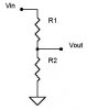
I want 9,6V/1,4A from a 24V (1700mA) battery. The way I wanted to do it was with a voltage divider, where:

R1: 10R2
R2: 6R8
All resistors must be around 15W

(The actual resitor values can only be obtained using a variable resistor)

Is this the best way of doing it, or do you have other surgestions?
 

Attachments

  • VD.JPG
    VD.JPG
    5.3 KB · Views: 240
Better way might be to use an LM317 regulator.

AllVol

Edit: NOTE: Avatar is even more appropriate since this message
just kicked me up to Electronics Master category.
 
Last edited:
LM317 (adjustable regulator) and heatsink. The resistors are a bad idea. Most of the battery will be wasted and it will probably run a little warm. :)

Again, what you are trying to power with this? 1.4AMP I doubt it.
 
That won't work unless you know exactly what the load resistance is (and it doesn't vary). Because the bottom resistor and the load resistance will be in parallel producing smaller resistance, and a lower voltage than you want.

It's best only to use resisitive dividers to bias things like MOSFETS since the load (the gate resistance) is "infinite" and won't skew the resistance of the bottom resistor, and also needs no current output..since the resistive divider can't effectively output current without distorting the voltage output.

PLus you got "short-circuit" currents which consume power.
 
Last edited:
Thanks for the "warnings"
I need to power up an electric accu power drill with a 24V/1,7A battery and also to control the motors speed controlling the voltage/current. The LM317 is a good surgestion for this circuit. What is it actually that controls the speed of a motor the voltage or the current, and are there better ways of controlling the speed of it. I want it to go slowly.

Thanks again
 
dknguyem is right. His load and R2, that is a good point if he needs regulated power.

Either way, he is on the right track now.
 
AllVol said:
Which "that" won't work ... the resistive divider or the lm317?
Sorry, the resistive divider won't work. The LM317 will.

What is it actually that controls the speed of a motor the voltage or the current, and are there better ways of controlling the speed of it. I want it to go slowly.
At no load, voltage is pretty much the only thing that determines motor speed. The more load you put on the motor, the more current it will draw. So voltage->speed, current->torque. BUT of course things aren't that simple, because as load (torque) increases, speed decreases. At a fixed voltage, an increasing load will cause the motor to draw more current and use it to apply more torque in an effort to maintain that maximum speed (which it obviously won't be able to unless the motor is seriously oversized and massive compared to the load. Even then it will slow down a smidgen.) Bigger motors have a shallower slope for their speed-torque graph which means that their speed is less sensitive to changes in torque/load than smaller motors which have a steeper speed-torque curve. This means if you apply X load to a large motor, it's RPM will decrease by less than if you apply X load to a smaller motor. Makes sense.

It's all a balance. You cannot blindly apply a voltage to get a motor to spin at a specific speed unless you know the load. The higher the load, the higher the voltage you must apply to get it to run at the same speed (and the more current it will draw as well). This is assuming of course, you can supply unlimited current regardless of the voltage and the motor doesn't heat up. There are practical limits.

For speed control, don't use a variable resistor- that is wasteful since it dissipates all extra voltage off as heat. Instead, for an inductive load like a motor, use PWM pulses. A frequency of 20kHz is good (too slow and the motor will noticeably pulse and too fast is inefficient for the electronics). The % duty cycle you apply is effectively the % of the full voltage seen by the motor.

Actually if you want it to always go at a speed significantly lower than it's maximum, you should gear it down a bit so you also get more force...it's pointless to run a undervolt a really fast motor to get it to move very slowly because it is too weak and doesn't output enough power to do anything.
 
Last edited:
At 20 watts ((24-9.6)*1.4) dissipation (assuming his numbers are correct), an LM317 is going to require one mozam heatsink. He really needs a switching regulator. I ain't gonna design one. :(
 
Drive the LM 317 in a 2N2955 so around 5 Amps is available.
a big heatsink is still required.
 
Hello. Is cheating and using National's Webench a valid option?

For 24V in, 9.6V @ 2A out, here's the BOM and schematic.

JR
 

Attachments

  • BOM.pdf
    4.4 KB · Views: 223
  • LM25005.pdf
    270.4 KB · Views: 229
There is no shame in cheating if you don't have a wafer foundry and design team to do it yourself.
 
Electronics4you said:
What is it actually that controls the speed of a motor

PWM, Google for "PWM motor speed controll" to find out more.
 
Status
Not open for further replies.

New Articles From Microcontroller Tips

Back
Top